Monthly Archives: July 2024

briggs and stratton motor repair manual

Briggs and Stratton motor repair manuals provide comprehensive guidance for maintaining and repairing small engines, covering various models, maintenance tips, and troubleshooting procedures for optimal performance.

1.1 Overview of Briggs and Stratton Engines

Briggs & Stratton engines are renowned for their reliability and versatility, powering a wide range of outdoor power equipment, including lawn mowers, generators, and pressure washers. They offer a variety of engine types, such as single-cylinder OHV and L-Head twin-cylinder models, designed for both residential and commercial use. Known for their durability and performance, these engines are built to withstand rigorous conditions. Whether it’s a small mower or a heavy-duty industrial application, Briggs & Stratton engines are trusted for their consistent power delivery and long service life, making them a preferred choice for many users worldwide.

1.2 Importance of Using Official Repair Manuals

Using official Briggs & Stratton repair manuals ensures accuracy and safety when maintaining or repairing engines. These manuals provide precise instructions tailored to specific engine models, minimizing the risk of errors. They include detailed troubleshooting guides, diagrams, and parts lists, essential for accurate diagnostics and repairs. Official manuals also highlight safety precautions, protecting users from potential hazards. By following manufacturer guidelines, users maintain engine integrity and ensure optimal performance. This adherence to official documentation is crucial for both novice and experienced technicians, guaranteeing reliable outcomes and prolonging engine lifespan.

1.3 Safety Precautions for Engine Repair

Always prioritize safety when performing engine repairs. Disconnect the spark plug wire to prevent accidental starts and ensure the engine is cool before beginning work. Wear protective gear, including gloves and safety glasses, to safeguard against sharp edges and debris. Work in a well-ventilated area to avoid inhaling harmful fumes. Never smoke or use open flames near flammable materials like fuel or oil. Follow all instructions in the official manual carefully, and avoid shortcuts that could lead to injuries or engine damage. Proper safety practices ensure a secure and effective repair process.

Understanding Briggs and Stratton Engine Models

Briggs and Stratton produces a wide range of small engines, including single-cylinder OHV, L-Head twin-cylinder, and various other models designed for diverse applications and power needs.

2.1 Single Cylinder OHV Engines

Single-cylinder OHV (Overhead Valve) engines by Briggs and Stratton are renowned for their efficiency and reliability, commonly powering lawn mowers, generators, and small equipment. These engines feature a compact design with a single piston and cylinder, making them lightweight and easy to maintain. The overhead valve configuration improves fuel efficiency and reduces emissions compared to older L-Head designs. They are ideal for applications requiring moderate power output, such as residential lawn care equipment. With a straightforward architecture, these engines are popular among DIY enthusiasts and professionals alike for their simplicity and durability in various operating conditions.

2.2 L-Head Twin Cylinder Engines

Briggs and Stratton L-Head Twin Cylinder engines are durable and versatile, often used in heavier applications like commercial lawn equipment and larger generators. These engines feature two cylinders with a side-valve design, offering a balance of power and efficiency. The L-Head configuration simplifies maintenance and repair, making them a favorite among professionals. Twin cylinders provide smoother operation and reduced vibration compared to single-cylinder models. They are ideal for demanding tasks and are known for their reliability under heavy loads. Regular maintenance, such as oil changes and valve adjustments, ensures optimal performance and longevity of these robust engines.

2.3 Model Number Identification

Identifying the correct model number of your Briggs and Stratton engine is crucial for accurate repair and maintenance. The model number is typically located on a data tag or label, often found on the engine shroud or cylinder. This number is unique to your engine and provides specific details about its specifications, horsepower, and configuration. Always use the exact model number when ordering parts or referencing repair manuals to ensure compatibility. Briggs and Stratton may substitute engines of higher power, so precise identification is essential for proper service and functionality. Refer to the engine manual or manufacturer’s website for guidance on locating and interpreting the model number.

Essential Tools and Equipment for Repair

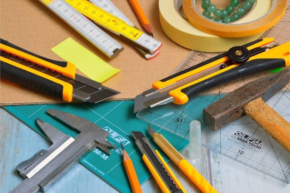
Essential tools for Briggs and Stratton engine repair include basic hand tools, such as wrenches and screwdrivers, and specialized tools like piston ring compressors and valve spring tools.

3.1 Basic Hand Tools

Basic hand tools are indispensable for Briggs and Stratton engine repairs. Essential tools include adjustable and fixed wrenches, screwdrivers (both flathead and Phillips), pliers, and a hammer. These tools enable disassembly, tightening, and adjusting engine components. Additionally, a socket set and torque wrench are often required for precise bolt tightening. Safety gloves and goggles should be worn to protect against potential hazards. Proper tool selection ensures efficient and safe repairs, preventing damage to engine parts. Always refer to the manual for specific tool recommendations tailored to your engine model. Keeping these tools organized and within reach streamlines the repair process.

3.2 Specialized Tools for Briggs and Stratton Engines

Specialized tools are crucial for specific Briggs and Stratton engine repairs. These include piston ring compressors for cylinder work, carburetor adjustment tools, and governor spring tools. A flywheel puller is often necessary for crankshaft repairs, while a spark tester ensures proper ignition systems; Specialized tools may also include timing gauges and compression testers for diagnosing engine performance issues. Always refer to the repair manual for a detailed list of required tools for your engine model. Using the correct tools ensures safe and effective repairs, preventing potential damage to engine components. Genuine Briggs and Stratton tools are recommended for compatibility and reliability.

Common Repair Procedures

Common repair procedures include oil changes, air filter cleaning, spark plug replacement, and fuel system maintenance. These tasks ensure optimal engine performance and longevity. Regular servicing prevents breakdowns and extends engine life. Always follow manual guidelines for precise instructions and safety.

4.1 Oil Change and Lubrication

Regular oil changes are essential for maintaining the health and performance of Briggs and Stratton engines. Always use the recommended oil type, such as SAE 30 for most conditions or synthetic oil for extreme temperatures. Check the oil level using the dipstick before starting the engine. Drain the old oil into a pan and replace the oil filter. Refill with the specified amount of new oil. Proper lubrication ensures engine components run smoothly, prevents overheating, and extends the engine’s lifespan. Dispose of used oil responsibly. Refer to the manual for specific instructions and recommended maintenance intervals.

4.2 Air Filter Maintenance

Proper air filter maintenance is crucial for ensuring optimal performance and longevity of Briggs and Stratton engines. Regularly inspect and clean or replace the air filter as recommended in the manual. Foam filters can be cleaned with soap and water, while paper filters should be replaced. A dirty air filter reduces engine power, increases fuel consumption, and may cause overheating. Always use genuine Briggs and Stratton air filters for compatibility and performance. Clean the filter housing and ensure it is securely installed after maintenance. Refer to the manual for specific instructions tailored to your engine model.

4.3 Spark Plug Replacement

Spark plug replacement is essential for maintaining efficient combustion in Briggs and Stratton engines. Always use the correct spark plug type, such as Champion RJ19LM or equivalent, as specified in the manual. Locate the spark plug on the cylinder head, remove the wire boot, and use a spark plug socket to extract the old plug. Inspect the spark plug for wear or fouling and install a new one, ensuring it is properly seated. Tighten the spark plug to the recommended torque to avoid damage. A faulty spark plug can cause engine misfires, poor performance, or failure to start, making regular replacement crucial for optimal functionality.

4.4 Fuel System Cleaning

Cleaning the fuel system is crucial for maintaining the performance and longevity of Briggs and Stratton engines. Over time, fuel residue and debris can accumulate, leading to clogs and poor engine operation. Start by draining old fuel and inspecting the fuel tank for sediment. Use a fuel system cleaning solution or a carburetor cleaner to remove deposits. Flush the fuel line and ensure the air filter is clean to prevent contamination. Replace the fuel filter and check for any blockages in the fuel intake. Regular cleaning prevents fuel-related issues and ensures proper engine combustion. Always refer to the manual for specific instructions and safety precautions.

Diagnosing Engine Problems

Diagnosing engine issues involves identifying symptoms, checking components, and using troubleshooting guides. Regular inspection and systematic analysis help pinpoint problems efficiently, ensuring timely repairs and optimal engine performance.

5.1 Identifying Common Issues

Identifying common issues in Briggs and Stratton engines involves recognizing symptoms like engine overheating, oil leaks, or poor performance. Troubleshooting guides in repair manuals help diagnose problems such as faulty spark plugs, clogged air filters, or carburetor malfunctions. Listening to unusual noises or observing decreased power output can also indicate underlying issues. Regular inspection of components like fuel lines, mufflers, and valves ensures early detection of potential failures. By systematically analyzing symptoms and referring to the manual, technicians and DIYers can pinpoint root causes and apply appropriate fixes to restore engine functionality and efficiency.

5.2 Using the Troubleshooting Guide

The troubleshooting guide in Briggs and Stratton repair manuals offers a systematic approach to diagnosing engine problems. It lists common symptoms, such as engine stalling or loss of power, and provides corresponding causes and solutions. By referring to the guide, users can identify issues like faulty spark plugs, clogged air filters, or fuel system blockages. The guide also includes step-by-step instructions for testing components and performing repairs. Its clear structure ensures efficient problem-solving, helping users restore engine performance without unnecessary delays or advanced technical knowledge.

Advanced Repair Techniques

The troubleshooting guide in Briggs and Stratton repair manuals helps identify and resolve common engine issues efficiently. It lists symptoms, potential causes, and repair steps, ensuring quick diagnostics and fixes for problems like poor performance or failure to start. By following the guide, users can address issues systematically, minimizing downtime and costly repairs. This section is essential for both novice and experienced technicians, providing clear, actionable solutions to restore engine functionality effectively.

6.1 Rebuilding the Engine

Rebuilding a Briggs and Stratton engine involves disassembling, inspecting, and replacing worn or damaged components. Start by removing the cylinder head, piston, and crankshaft. Clean and inspect all parts for wear. Replace bearings, seals, and gaskets with genuine Briggs and Stratton parts to ensure reliability. Reassemble the engine in the reverse order of disassembly, applying proper torque specifications. Use specialized tools, such as piston ring compressors, to simplify the process. After rebuilding, perform a test run to check for leaks or unusual noises. Proper rebuilding restores engine performance and extends its lifespan, ensuring optimal operation for years to come.

6.2 Repairing the Starter Motor

Repairing the starter motor on a Briggs and Stratton engine involves diagnosing and addressing common issues such as worn brushes, faulty solenoids, or damaged gears. Begin by disconnecting the battery and removing the starter motor from the engine. Disassemble the motor to inspect internal components for wear or damage. Replace any faulty parts, such as brushes or bearings, using genuine Briggs and Stratton replacement parts. Reassemble the motor, ensuring proper alignment and secure connections. Test the starter motor by reconnecting it to the engine and checking for smooth operation. Regular maintenance and timely repairs prevent starter failure and ensure reliable engine starting.

6.3 Adjusting the Governor

Adjusting the governor on a Briggs and Stratton engine ensures proper engine speed regulation, maintaining performance and safety. Start by disconnecting the spark plug wire to prevent accidental starts. Locate the governor adjustment screw, typically found on the engine’s carburetor or governor housing. Loosen the screw slightly, then turn it clockwise to increase RPM or counterclockwise to decrease RPM. Refer to the repair manual for specific RPM settings. After adjustment, tighten the screw and reconnect the spark plug wire. Test the engine under various loads to ensure smooth operation and proper governor response. Always follow safety guidelines and consult the manual for precise instructions.

Parts Replacement and Upgrades

Replacing worn or damaged parts with genuine Briggs and Stratton components ensures optimal engine performance. Upgrades can enhance efficiency and power. Always refer to the manual for compatibility and installation guidelines.

7.1 Ordering Genuine Briggs and Stratton Parts

Ordering genuine Briggs and Stratton parts ensures compatibility and performance. Use the model number from your engine to identify the correct components. Refer to the parts manual or illustrated parts list for accuracy. Contact Briggs & Stratton directly or visit authorized service centers for authentic parts. Online resources like official websites or forums can also guide you. Always verify the part number before purchase to avoid mismatches. Using genuine parts guarantees safety, reliability, and optimal engine operation. Avoid non-genuine parts, as they may void warranties or compromise performance. For assistance, call the toll-free number provided in the manual.

7.2 Installing Replacement Parts

Installing replacement parts requires careful adherence to the repair manual’s instructions. Ensure all components are genuine Briggs & Stratton parts for compatibility. Use specialized tools as recommended to avoid damage. Follow torque specifications and safety guidelines to prevent accidents. Refer to diagrams in the manual for proper assembly. Test the engine after installation to ensure functionality. Avoid common mistakes like over-tightening or misaligning parts. If unsure, consult the troubleshooting guide or contact an authorized service center. Proper installation ensures optimal performance, safety, and longevity of the engine.

Seasonal Maintenance and Storage

Seasonal maintenance ensures your engine performs efficiently year-round. Winterize by draining fuel and protecting components. Store in a clean, dry area with a breathable cover. Regular checks prevent damage.

8.1 Winterizing the Engine

Winterizing your Briggs and Stratton engine is crucial for preserving its longevity. Start by draining the fuel tank and lines to prevent corrosion and stale fuel issues. Use a fuel stabilizer if you prefer to keep some fuel in the system. Disconnect the spark plug wire and clean or replace the spark plug as needed. Apply a rust-inhibiting oil to moving parts and cover the engine to protect it from moisture. Store the engine in a dry, well-ventilated area to avoid condensation damage. Regularly inspect stored engines to ensure they remain in good condition.

8.2 Preparing for Summer Use

Preparing your Briggs and Stratton engine for summer use involves several key steps to ensure optimal performance. Begin by inspecting the fuel system, draining any old or stale fuel, and refilling with fresh gasoline. Check the air filter and replace it if dirty or damaged. Reconnect the spark plug wire and ensure the spark plug is clean or replaced. Lubricate moving parts to prevent rust and wear. Test the engine by running it under light load to ensure smooth operation. Address any issues identified during the test to guarantee reliability during the summer season.

Using the Repair Manual Effectively

Understand and apply the manual’s guidelines for repairs, utilizing diagrams and troubleshooting sections to ensure accurate and efficient maintenance of your Briggs and Stratton engine.

9.1 Navigating the Manual

Navigating a Briggs and Stratton repair manual is straightforward with its organized structure. Begin by reviewing the table of contents to locate specific sections, such as maintenance, troubleshooting, or parts replacement. Use the index to quickly find detailed procedures or diagrams relevant to your engine model. The manual is divided into numbered sections, with clear headings and subheadings for easy reference. Pay attention to safety precautions and warnings highlighted throughout. Familiarize yourself with the visual aids, such as exploded diagrams, to better understand complex components. By following this logical flow, you can efficiently locate the information needed for your repair or maintenance tasks.

9.2 Understanding Diagrams and Illustrations

Diagrams and illustrations in Briggs and Stratton repair manuals are essential for visualizing engine components and repair steps; Exploded views detail how parts fit together, aiding in disassembly and reassembly. Wiring diagrams simplify electrical system troubleshooting, while flowcharts guide logical diagnostics. Icons and symbols are consistently used to represent common actions or components. Always refer to the legend or key provided to interpret these visuals accurately. By studying these diagrams, you can better understand the relationships between engine parts and follow procedures more confidently, ensuring repairs are done correctly and safely. Cross-referencing text with visuals enhances comprehension and minimizes errors. Color-coded elements further simplify identification of critical components. This visual support is a cornerstone of effective manual usage, helping users avoid mistakes and complete tasks efficiently. Proper interpretation of diagrams is crucial for successful repairs and maintaining engine performance. Regularly review and cross-reference visuals with written instructions to ensure accuracy and safety in all procedures. Understanding these illustrations is key to mastering engine repair and maintenance. They provide a clear, actionable guide that complements the written content, making complex tasks more approachable. Utilize these resources to enhance your repair skills and ensure long-term engine reliability. Proper use of diagrams ensures that even novice technicians can achieve professional results; By combining textual instructions with visual guides, the manual offers a comprehensive toolkit for engine servicing. This dual approach simplifies troubleshooting and repair, making it accessible to a wide range of users. Always take the time to thoroughly examine and understand the diagrams before starting any repair work. They are designed to be your primary visual reference, ensuring that each step is executed with precision and care. Familiarizing yourself with the manual’s illustrative style will improve your efficiency and confidence in handling engine repairs. Use these visuals to identify potential issues, plan your approach, and execute repairs effectively. The combination of clear visuals and detailed text creates a robust resource for maintaining and repairing Briggs and Stratton engines. By leveraging both, you can address a wide range of engine needs, from routine maintenance to complex overhauls. Understanding and applying the information in these diagrams is essential for achieving optimal results and ensuring the longevity of your engine. This integrated approach to instruction is a hallmark of Briggs and Stratton repair manuals, making them indispensable for technicians and DIY enthusiasts alike. Always rely on these visuals to guide your work and confirm that each step aligns with the manual’s recommendations. Properly interpreting diagrams ensures that repairs are both effective and safe, minimizing the risk of further damage or injury. By mastering the visual language of the manual, you can tackle even the most challenging engine issues with confidence and precision. The diagrams are your roadmap to successful repairs, so use them wisely to navigate the complexities of engine maintenance. They are an invaluable resource that, when combined with the written instructions, provide a complete guide for engine servicing. Always refer to these visuals to confirm your understanding and ensure that your repairs meet the highest standards of quality and safety. The careful study of diagrams and illustrations is a critical step in any repair process, and their proper interpretation is essential for achieving the desired outcomes. By utilizing these visual tools effectively, you can overcome technical challenges and maintain your engine’s peak performance. The combination of textual and visual information in the manual creates a powerful resource that supports both learning and application, making it an essential companion for anyone working with Briggs and Stratton engines. Understanding and applying the information in these diagrams is key to successful engine repair and maintenance. Always take the time to carefully review and interpret these visuals before starting any procedure, as they provide the clarity and precision needed to achieve professional results. Proper use of diagrams ensures that repairs are performed safely, efficiently, and effectively, preserving the engine’s functionality and longevity. By integrating visual and textual information, the manual offers a comprehensive guide that empowers users to address a wide range of engine needs with confidence and expertise. Always rely on these diagrams to navigate the repair process, confirming each step and ensuring that your work aligns with the manufacturer’s recommendations. The careful interpretation of visuals is a cornerstone of successful engine maintenance, and their proper use is essential for achieving optimal results. By mastering the manual’s illustrative content, you can enhance your repair skills and ensure that your engine operates at its best for years to come. The combination of clear visuals and detailed text makes the manual an indispensable resource for both novice and experienced technicians, providing the tools needed to tackle even the most complex engine challenges. Always use these diagrams to guide your work, ensuring that each repair is performed with precision and care. Proper interpretation of visuals is critical for maintaining safety, efficiency, and effectiveness in all engine repair tasks. By leveraging the manual’s illustrative content, you can overcome technical obstacles and achieve professional-quality results, ensuring the reliability and performance of your Briggs and Stratton engine. The diagrams are your visual guide to successful repairs, so use them wisely to navigate the complexities of engine maintenance and servicing. Always refer to these visuals to confirm your approach and ensure that your work meets the highest standards of quality and safety. The careful study and application of diagrams and illustrations are essential for achieving the best outcomes in engine repair and maintenance. By understanding and utilizing these visual tools effectively, you can enhance your repair skills and maintain your engine’s peak performance for years to come. The combination of textual and visual information in the manual creates a robust resource that supports both learning and application, making it an essential companion for anyone working with Briggs and Stratton engines. Always take the time to thoroughly examine and interpret these visuals before starting any repair work, as they provide the clarity and precision needed to achieve professional results. Proper use of diagrams ensures that repairs are performed safely, efficiently, and effectively, preserving the engine’s functionality and longevity. By integrating visual and textual information, the manual offers a comprehensive guide that empowers users to address a wide range of engine needs with confidence and expertise. Understanding and applying the information in these diagrams is key to successful engine repair and maintenance. Always rely on these visuals to guide your work and confirm that each step aligns with the manual’s recommendations. Properly interpreting diagrams ensures that repairs are both effective and safe, minimizing the risk of further damage or injury. By mastering the visual language of the manual, you can tackle even the most challenging engine issues with confidence and precision. The diagrams are your roadmap to successful repairs, so use them wisely to navigate the complexities of engine maintenance. They are an invaluable resource that, when combined with the written instructions, provide a complete guide for engine servicing. Always refer to these visuals to confirm your understanding and ensure that your repairs meet the highest standards of quality and safety. The careful study of diagrams and illustrations is a critical step in any repair process, and their proper interpretation is essential for achieving the desired outcomes. By utilizing these visual tools effectively, you can overcome technical challenges and maintain your engine’s peak performance. The combination of textual and visual information in the manual creates a powerful resource that supports both learning and application, making it an essential companion for anyone working with Briggs and Stratton engines. Understanding and applying the information in these diagrams is key to successful engine repair and maintenance. Always take the time to carefully review and interpret these visuals before starting any procedure, as they provide the clarity and precision needed to achieve professional results. Proper use of diagrams ensures that repairs are performed safely, efficiently, and effectively, preserving the engine’s functionality and longevity. By integrating visual and textual information, the manual offers a comprehensive guide that empowers users to address a wide range of engine needs with confidence and expertise. Always rely on these diagrams to navigate the repair process, confirming each step and ensuring that your work aligns with the manufacturer’s recommendations. The careful interpretation of visuals is a cornerstone of successful engine maintenance, and their proper use is essential for achieving optimal results. By mastering the manual’s illustrative content, you can enhance your repair skills and ensure that your engine operates at its best for years to come. The combination of clear visuals and detailed text makes the manual an indispensable resource for both novice and experienced technicians, providing the tools needed to tackle even the most complex engine challenges. Always use these diagrams to

Additional Resources for Repair

Online forums, authorized service centers, and downloadable PDF manuals provide valuable support for Briggs and Stratton engine repairs, offering expert advice, troubleshooting tips, and detailed repair guides.

10.1 Online Forums and Communities

Online forums and communities are invaluable resources for Briggs and Stratton engine repair. Websites like Repair Forums, Small Engine Repair, and enthusiast groups offer troubleshooting tips, repair guides, and real-time advice from experienced technicians and DIYers. Many forums feature downloadable repair manuals, diagrams, and discussions on common issues, such as starter motor problems or fuel system cleaning. Users can share their experiences, ask specific questions, and receive tailored solutions. These platforms foster collaboration, helping users diagnose and resolve engine problems efficiently. Active participation in these communities ensures access to up-to-date information and expert insights, enhancing your repair skills and confidence.

10.2 Authorized Service Centers

Authorized Briggs and Stratton service centers are trusted resources for professional engine repair and maintenance. These centers employ certified technicians with extensive experience in diagnosing and fixing engine issues. They use genuine Briggs and Stratton parts, ensuring reliability and compliance with manufacturer standards. To locate an authorized service center, visit the official Briggs and Stratton website or call their toll-free customer support line. These centers also offer specialized tools and adhere to safety protocols, providing high-quality service for routine maintenance, complex repairs, and warranty-related work. Their expertise guarantees efficient and durable solutions for your engine needs.

Briggs and Stratton motor repair manuals are essential resources for maintaining and repairing engines. Regular maintenance and using genuine parts ensure longevity and optimal performance.

11.1 Final Tips for Successful Repairs

Always adhere to the repair manual’s instructions for precise guidance; Ensure safety by wearing protective gear and following precautions. Use genuine Briggs & Stratton parts for reliability. Start with basic diagnostics before proceeding to complex repairs. Keep the workspace clean and well-lit for visibility. Refer to troubleshooting guides for common issues. Test the engine thoroughly after repairs to ensure proper function. Consult online forums or authorized service centers if stuck. Regular maintenance can prevent future breakdowns. By following these tips, you’ll achieve successful repairs and extend your engine’s lifespan.

11.2 Importance of Regular Maintenance

Regular maintenance is crucial for extending the lifespan and performance of Briggs & Stratton engines. It helps prevent unexpected breakdowns and ensures reliability. Simple tasks like oil changes, air filter cleaning, and spark plug replacements can significantly improve efficiency. Refer to the repair manual for a detailed schedule tailored to your engine model. Neglecting maintenance can lead to costly repairs and reduced power output. By staying proactive, you safeguard your investment and ensure optimal functionality. Always follow the recommended maintenance routines to keep your engine running smoothly and efficiently throughout its operational life.

pro series 2400 sump pump manual

The Pro Series 2400 is a reliable battery backup sump pump system designed to provide emergency water removal during power outages or primary pump failure.

1.1 Overview of the Pro Series 2400 Model

The Pro Series 2400 is a high-performance battery backup sump pump system designed to provide reliable emergency water removal. With a flow rate of 2,400 gallons per hour at a 10-foot lift, it ensures efficient pumping during power outages or primary pump failure. The system features a dual float switch for added reliability and an advanced alarm and monitoring system for real-time notifications. Its robust design and compatibility with existing AC sump pumps make it a comprehensive solution for protecting homes from water damage. The Pro Series 2400 offers peace of mind with its automatic backup capabilities and user-friendly operation.

1.2 Importance of the Manual for Safe Operation

The manual is essential for the safe and proper operation of the Pro Series 2400 sump pump system. It contains critical safety warnings, installation guidelines, and maintenance instructions to prevent accidents and ensure reliable performance. Even if installed by a professional, reading the manual is crucial to understand system operation, potential hazards, and troubleshooting steps. Failure to follow the instructions can lead to property damage, personal injury, or system malfunction. The manual also provides detailed information on electrical safety and battery care, ensuring the system functions correctly during emergencies.

Safety Precautions and Warnings

Follow all safety guidelines to avoid injury or damage. Ensure proper electrical connections, handle batteries carefully, and keep the system out of reach of children.

2.1 General Safety Guidelines

Always read and follow the manual carefully to ensure safe operation. Keep the system out of reach of children and avoid touching electrical components with wet hands. Never overload the battery or use incompatible accessories. Proper installation and maintenance are crucial to prevent malfunctions. Ensure the sump pit is clear of debris and the pump is level. Avoid exposing the system to extreme temperatures or corrosive substances. Failure to adhere to these guidelines may result in damage, injury, or void the warranty. Regular inspections are essential to maintain reliability and performance.

2.2 Electrical Safety Considerations

Ensure all electrical connections are secure and meet local codes. Use a dedicated 20-amp GFCI-protected circuit for the system. Avoid overloading circuits with other appliances. Never use damaged cords or incorrect voltage ratings. Keep the battery away from open flames or sparks. Disconnect power before servicing. Grounding must be properly installed to prevent shock. Failure to follow electrical safety guidelines can lead to fire hazards, electrical shock, or system damage. Always consult a licensed electrician if unsure about any connections or requirements.

2.3 Handling and Installation Precautions

Handle the Pro Series 2400 system with care to avoid damage. Always lift the pump by the metal frame, never by the battery or hoses. Ensure the sump pit is clear of debris before installation. Discharge pipes must be parallel to the floor to prevent airlocks. Use only compatible batteries and avoid mixing old and new ones. Tighten connections firmly but avoid over-tightening. Test the system after installation to ensure proper function. Wear protective gloves and eyewear during installation and maintenance to prevent injury from sharp edges or acid spills.

System Components and Features

The Pro Series 2400 includes a powerful main pump, backup battery, dual float switches, and an advanced alarm system for reliable water removal and real-time monitoring.

3.1 Main Pump Unit

The main pump unit of the Pro Series 2400 is a high-performance submersible sump pump capable of pumping up to 2400 gallons per hour at a 10-foot lift. Designed for continuous duty during power outages, it features a durable, corrosion-resistant construction. The pump includes dual float switches for automatic operation, ensuring reliable water removal even in extreme conditions. Its advanced motor design provides quiet and efficient operation, making it ideal for residential and light commercial applications. The unit is also equipped with thermal overload protection to prevent damage from overheating.

3.2 Backup Battery System

The Pro Series 2400 includes a robust backup battery system designed to provide continuous operation during power outages. The system features a high-capacity battery that can run the pump for up to 8 hours under normal conditions. Advanced monitoring ensures the battery is always charged and ready for emergencies. The backup system automatically activates if the primary pump fails, offering unparalleled reliability. It also includes thermal protection to prevent overheating and extend battery life. This ensures your sump pump remains functional, even during extended power failures or extreme weather events.

3.3 Float Switch Mechanism

The Pro Series 2400 features a dual float switch mechanism designed to activate the pump during rising water levels. This system ensures reliable operation by detecting water level changes and triggering the pump automatically. The float switch is durable and corrosion-resistant, providing long-term performance. Proper installation ensures the switch operates smoothly, preventing pump tilting and wear. Regular inspection is recommended to maintain optimal functionality. The dual design enhances redundancy, ensuring continuous protection against water accumulation, even during power outages or primary pump failure.

3.4 Alarm and Monitoring System

The Pro Series 2400 includes an advanced alarm and monitoring system that provides real-time notifications for system status and potential issues. It alerts homeowners of high water levels, pump activation, or battery-related problems. The system ensures timely intervention, preventing property damage. With features like remote notifications, users can monitor the sump pump from anywhere, offering peace of mind. The alarm is loud and clear, ensuring immediate awareness of system events. This comprehensive monitoring solution enhances the overall reliability and efficiency of the backup sump pump system.

Installation Instructions

Follow step-by-step guidelines to ensure proper installation of the Pro Series 2400 system, including preparing the sump pit, connecting the pump, and configuring the float switch.

4.1 Preparing the Sump Pit

Before installing the Pro Series 2400, ensure the sump pit is clean and free of debris. Check the pit’s size to accommodate the pump and backup system. Verify that the discharge pipes are properly aligned and secured. Ensure the sump pump and backup battery are placed on a stable, level surface. Refer to the manual for specific measurements and configuration requirements to guarantee optimal performance and safety during operation.

4.2 Connecting the Pump and Battery

Connect the Pro Series 2400 pump and battery following the manual’s guidelines. First, unpack and inspect all components for damage. Attach the battery terminals securely, ensuring correct polarity. Connect the discharge pipe to the pump outlet, ensuring a watertight seal. Use the provided hardware to secure the pump in the sump pit. Double-check all connections for tightness and proper alignment. Finally, test the system by simulating a power outage to ensure the backup activates correctly. Always follow safety precautions to avoid electrical hazards or system damage.

4.3 Configuring the Float Switch

Configure the float switch to ensure proper activation of the backup pump. Adjust the switch to trigger at the desired water level, ensuring it moves freely without obstructions. Secure the float switch to the discharge pipe, maintaining alignment for accurate sensing. Test the switch by manually lifting it to confirm the backup pump activates. Ensure the switch is properly seated and aligned to prevent over-pumping or failure to engage. Regularly inspect the float switch for debris or wear to maintain reliable operation. Proper configuration is critical for the system’s effectiveness during power outages or primary pump failure.

4.4 Final System Check

After installation, perform a final system check to ensure all components function correctly. Test the primary and backup pumps by simulating a power outage. Verify the float switch activates both pumps at the correct water levels. Check the alarm system to ensure it sounds when the backup mode is engaged; Inspect the discharge pipes for proper flow and connections. Test the battery voltage and ensure it is fully charged. Review all connections for tightness and integrity. Finally, simulate a high-water scenario to confirm the system operates seamlessly. This step ensures reliable performance during emergencies.

Operating the Pro Series 2400

The Pro Series 2400 operates automatically, switching between AC power and battery backup during outages. It ensures continuous water removal, providing peace of mind during emergencies.

5.1 Normal Operation Mode

In normal operation, the Pro Series 2400 functions as a reliable backup system, automatically switching to battery power during AC outages. The pump activates when the float switch detects rising water levels, ensuring continuous protection. It seamlessly integrates with your primary sump pump, providing uninterrupted water removal. The system monitors water levels and battery status, offering advanced monitoring capabilities for peace of mind. Designed for efficiency, it ensures your basement remains dry and secure under normal conditions.

5.2 Backup Mode Activation

The Pro Series 2400 activates its backup mode during power outages or primary pump failure. The float switch triggers the battery-operated pump when water levels rise, ensuring continuous protection. The system automatically switches to DC power, maintaining operation without manual intervention. This seamless transition guarantees uninterrupted water removal, providing peace of mind during emergencies. The backup mode is designed to function independently, offering reliable performance until the primary power source is restored or the main pump resumes operation.

5.3 Monitoring the System

The Pro Series 2400 features an advanced monitoring system to ensure optimal performance. The built-in alarm alerts you to any issues, such as high water levels or pump malfunctions, providing immediate notifications. Users can monitor the system remotely using a Pro Series device, offering real-time updates and peace of mind. Regular checks of the alarm and battery status are recommended to ensure reliability. For detailed monitoring instructions, refer to the manual, which outlines steps for seamless system oversight and maintenance. This ensures your sump pump operates efficiently and reliably year-round.

Maintenance and Troubleshooting

Regular maintenance ensures the Pro Series 2400 operates efficiently. Check the battery, float switch, and discharge pipes for blockages. Troubleshoot common issues like pump failure or alarm triggers, and replace worn parts as needed to ensure reliability and prevent water damage.

6;1 Regular Maintenance Tasks

Regular maintenance is crucial to ensure the Pro Series 2400 operates efficiently; Inspect the battery terminals for corrosion and clean them if necessary. Check the battery water levels monthly and top them off as needed. Ensure the float switch moves freely without obstructions. Clear debris from the sump pit and discharge pipes to prevent blockages. Test the alarm system periodically to confirm it’s functioning properly. Lubricate moving parts and replace worn components to maintain performance. Schedule annual professional inspections to address any hidden issues and ensure the system remains reliable during emergencies.

6.2 Common Issues and Solutions

The Pro Series 2400 may encounter issues like alarm malfunctions or reduced pumping capacity. For alarm issues, check connections and ensure the system is properly powered. If the pump runs continuously, inspect the float switch for proper adjustment or obstructions. Low battery performance may indicate aging or incorrect charging; test the battery and replace it if necessary. Clogged discharge pipes can cause reduced flow; clear blockages promptly. Addressing these issues promptly ensures reliable operation and prevents potential system failure during emergencies. Always refer to the manual for specific troubleshooting guidance.

6.3 Battery Care and Replacement

Regularly inspect the battery terminals for corrosion and clean them to ensure proper connections. Avoid overcharging, as it can reduce battery life. Test the battery voltage annually and replace it every 5-7 years or when performance declines. Use only compatible, deep-cycle batteries to maintain system efficiency. If the battery is not holding charge, check for faulty charging systems. Always follow safety guidelines when handling batteries to prevent acid spills and electrical hazards. Refer to the manual for specific replacement procedures to ensure optimal system performance and reliability during emergencies.

Technical Specifications

The Pro Series 2400 offers 2400 GPH at 10 ft. lift, featuring a reliable backup battery system and compatibility with various sump pump configurations and setups.

7.1 Pump Performance Ratings

The Pro Series 2400 delivers a maximum flow rate of 2,400 gallons per hour (GPH) at a 10-foot lift, ensuring efficient water removal during emergencies. Its robust design and energy-efficient operation make it suitable for demanding applications. The pump maintains consistent performance across various lift heights, providing reliable protection against water accumulation. With a focus on durability, the system is engineered to handle frequent use while minimizing wear and tear. These ratings ensure the Pro Series 2400 meets the needs of residential and light commercial sump pump applications effectively.

7.2 Battery Specifications

The Pro Series 2400 system utilizes a compatible wet cell battery, designed for reliable backup power during outages. The battery operates at 12 volts and has a capacity sufficient for up to 8 hours of continuous operation. Proper charging and maintenance are essential to ensure optimal performance. The system is compatible with specific wet cell batteries, and using unauthorized models may void warranty or affect functionality; Regular testing and inspection of the battery are recommended to maintain its efficiency and longevity, ensuring the pump operates seamlessly during emergencies.

7;4 System Compatibility

The Pro Series 2400 is designed to integrate seamlessly with standard sump pump systems and compatible accessories. It works effectively with most primary AC sump pumps, ensuring a reliable backup solution. The system is also compatible with optional monitoring devices for remote notifications. However, compatibility with non-recommended batteries or unauthorized components may affect performance. Using genuine Glentronics parts ensures optimal functionality. Always refer to the manual for a list of approved accessories and components to maintain system efficiency and warranty validity.

Warranty and Support Information

The Pro Series 2400 is backed by a limited warranty covering manufacturing defects. Contact customer support for assistance with repairs, replacements, or technical inquiries. Visit our website for detailed warranty terms and support options.

8.1 Warranty Coverage Details

The Pro Series 2400 sump pump system is covered by a limited warranty that protects against manufacturing defects. The warranty period varies depending on the specific components, with the pump and battery typically covered for a set number of years. For exact terms, refer to the official manual or contact the manufacturer. The warranty ensures repairs or replacements for defective parts, providing peace of mind for homeowners; Proper installation and maintenance are required to maintain warranty validity. Visit the manufacturer’s website for detailed warranty conditions and claims procedures.

8.2 Contacting Customer Support

For assistance with the Pro Series 2400 sump pump system, customers can contact Glentronics, Inc. through their official website or by phone. The support team is available to address technical inquiries, troubleshooting, and warranty-related questions. Visit the support page for detailed contact information, including phone numbers and email. Additionally, the website offers downloadable resources, FAQs, and user manuals to help resolve common issues. For urgent matters, live chat or 24/7 phone support may be available. Always have the model number and serial number ready for efficient service.

Additional Resources

Access the full Pro Series 2400 manual, FAQs, and technical specifications online. Visit the official website for downloadable resources, troubleshooting guides, and detailed product information.

9.1 Downloading the Full Manual

The complete Pro Series 2400 sump pump manual is available for download on the official website. This comprehensive guide includes detailed installation, operation, and maintenance instructions. It also covers safety precautions, technical specifications, and troubleshooting tips. Users can access the manual in PDF format, ensuring easy viewing and printing. The document is essential for understanding system functionality and ensuring optimal performance. Visit the manufacturer’s website or authorized distributors to download the latest version of the manual for accurate and up-to-date information.

9.2 Online Support and FAQs

The official website offers extensive online support and FAQs for the Pro Series 2400 sump pump system. Users can access troubleshooting guides, installation tips, and maintenance advice. The FAQs section addresses common questions about system operation, battery care, and alarm functionality. Additionally, customers can contact technical support via email or phone for personalized assistance. Online resources also include downloadable brochures and manuals, ensuring users have comprehensive guidance. This support system provides round-the-clock access to information, helping users resolve issues quickly and efficiently.

steps to salvation billy graham pdf

Billy Graham’s teachings emphasize a clear path to salvation through faith in Jesus Christ, offering a simple, four-step plan rooted in biblical truths and God’s grace.

Overview of Billy Graham’s Ministry and Legacy

Billy Graham was a renowned evangelist whose ministry spanned over seven decades, impacting millions worldwide. Known for his clarity and simplicity, he presented the Gospel in a way that transcended denominations and cultures. Graham’s legacy includes his crusades, which brought people together to hear the message of salvation, as well as his use of media to spread the Gospel globally. He emphasized a personal relationship with Jesus Christ and promoted a four-step plan to salvation. Graham also authored numerous books and founded the Billy Graham Evangelistic Association, which continues his work today. His son, Franklin Graham, carries on his father’s mission, ensuring the message of salvation remains relevant. Billy Graham’s humanitarian efforts and commitment to unity earned him respect worldwide, solidifying his place as one of the most influential Christian leaders of the 20th century.

The Central Message of Salvation in Billy Graham’s Preachings

Billy Graham’s central message focused on the transformative power of salvation through faith in Jesus Christ. He consistently emphasized that salvation is a free gift from God, made possible by Christ’s sacrifice on the cross. Graham taught that humanity’s separation from God is due to sin, but through repentance and faith, individuals can experience spiritual rebirth. His teachings highlighted the simplicity of salvation, often summarizing it in four steps: recognizing the need for salvation, understanding sin’s consequences, accepting God’s solution through Christ, and receiving Jesus as Lord and Savior. Graham’s preaching was characterized by clarity, urgency, and hope, urging people to accept Christ personally. He stressed that salvation leads to eternal life and a life-changing relationship with God, offering assurance and peace to all who believe.

The Four Steps to Salvation According to Billy Graham

Billy Graham outlined a four-step path to salvation: recognizing your need, understanding sin’s consequences, accepting God’s solution through Christ, and receiving Jesus as Lord.

Step 1: Recognize Your Need for Salvation

Billy Graham taught that the first step to salvation is recognizing one’s need for it. This involves acknowledging sinfulness and separation from God, understanding that everyone falls short of His glory. Recognizing this need is not about comparing oneself to others but humbly admitting one’s spiritual bankruptcy before God. Graham emphasized that salvation begins with a personal conviction of sin, which the Holy Spirit often brings. Without this recognition, there can be no genuine desire to seek salvation. This step is foundational, as it opens the heart to the reality of sin and the necessity of a Savior. It is a call to humility and honesty, inviting individuals to acknowledge their need for divine intervention and pardon. This recognition is not about self-condemnation but about seeing the need for God’s grace and redemption.

Step 2: Understand the Problem of Sin and Separation from God

Billy Graham emphasized that sin is the root cause of humanity’s separation from God. The Bible teaches that sin creates a chasm between God and humanity, preventing us from experiencing His presence and eternal life. Graham often quoted Romans 3:23, which states, “For all have sinned and fall short of the glory of God.” This step involves recognizing that sin is not just wrongdoing but a fundamental rebellion against God’s holiness. Without addressing this spiritual problem, true salvation cannot occur. Graham stressed that sin leads to spiritual death and eternal separation from God unless resolved through Christ. Understanding this truth humbles the heart and prepares it to seek God’s solution. This step is crucial because it reveals the gravity of sin and the urgent need for redemption, laying the groundwork for the next step in the salvation process.

Step 3: Accept God’s Solution Through the Cross of Jesus Christ

Billy Graham repeatedly emphasized that God provided a solution to humanity’s sin problem through the cross of Jesus Christ. He taught that sin required a sacrifice, and Jesus, as the perfect Son of God, willingly died to pay the penalty for humanity’s sins. This step involves acknowledging that Jesus’ death was a substitutionary act of love, where He bore the punishment for sin on behalf of all people. Graham often highlighted that the cross represents God’s justice and mercy meeting, offering forgiveness and reconciliation. Accepting this solution requires faith in Jesus’ sacrifice and recognizing that salvation is a gift from God, not something earned. Graham stressed that the cross is the only bridge that spans the chasm between God and humanity, making it the central focus of salvation. This step is foundational because it reveals God’s profound love and the ultimate solution to sin.

Step 4: Receive Jesus Christ as Your Lord and Savior

Step 4 in Billy Graham’s plan of salvation is to personally receive Jesus Christ as your Lord and Savior. This step involves making a conscious decision to accept Jesus into your life, trusting in His death and resurrection as the payment for your sins. Graham emphasized that salvation is not merely intellectual agreement but a heartfelt commitment. He encouraged believers to repent of their sins, turning away from them, and to place their faith entirely in Jesus. This step is often accompanied by a prayer, such as asking Jesus to forgive sins and inviting Him to take control of one’s life. Graham stressed that receiving Christ is a transformative experience, leading to spiritual rebirth and a new relationship with God. This final step completes the journey to salvation, offering assurance of eternal life and fellowship with God.

Key Concepts in Billy Graham’s Plan of Salvation

Billy Graham’s plan emphasizes faith, repentance, and God’s grace, using the Bridge to Life illustration to show humanity’s separation from God and Jesus as the solution through His sacrifice.

The Bridge to Life Illustration

Billy Graham’s Bridge to Life illustration simplifies the plan of salvation, visually representing humanity’s separation from God due to sin. The illustration depicts a chasm between God and humanity, with Jesus Christ as the bridge spanning the gap. Step 1 emphasizes God’s love and purpose for humanity, offering peace and eternal life through Jesus. Step 2 addresses the problem of sin, which creates a separation from God. Step 3 introduces the cross as God’s solution, where Jesus sacrificially died to bridge the divide. Step 4 calls individuals to respond by receiving Christ through faith and repentance. This visual tool effectively communicates the gospel, making it accessible and memorable for millions worldwide.

The Role of Faith in Salvation

Faith is central to Billy Graham’s teachings on salvation, as it is the means by which individuals receive God’s grace. Graham emphasizes that faith is not merely intellectual belief but a heartfelt trust in Jesus Christ as Lord and Savior. He often quoted Scripture, such as Ephesians 2:8-9, to illustrate that salvation is a gift of God, not achieved through works. Faith involves surrendering to Christ, acknowledging sin, and trusting in His sacrifice on the cross. Graham taught that true faith leads to a transformed life, demonstrating a commitment to following Christ. He encouraged believers to place their faith in God’s promises, assuring them of eternal life and a personal relationship with Him. This emphasis on faith reflects Graham’s belief in the power of the gospel to transform lives and secure eternal salvation.

The Importance of Repentance

Repentance is a cornerstone of Billy Graham’s teachings on salvation, emphasizing the need to turn away from sin and toward God. Graham often stressed that repentance is not just a feeling of regret but a deliberate decision to abandon sinful ways and seek forgiveness. This step involves acknowledging one’s sinfulness and taking responsibility for it, as outlined in Scripture. According to Graham, repentance is closely tied to faith, as it prepares the heart to receive Christ. He frequently referenced biblical passages like Acts 3:19, which calls for repentance and turning to God. Graham taught that true repentance leads to a changed life, as individuals surrender to God’s will and seek His transformation. This principle remains central to his message, highlighting the necessity of repentance for experiencing salvation and living a life transformed by God’s grace.

Billy Graham’s Emphasis on Personal Transformation

Billy Graham emphasized that salvation leads to personal transformation, turning from sin, believing in Jesus, and living a new life in fellowship with God and others.

Salvation as a Life-Changing Experience

Billy Graham frequently emphasized that salvation is not merely a theological concept but a life-altering encounter with God. He taught that true salvation transforms an individual’s heart, mind, and lifestyle. This transformation begins with recognizing one’s sinfulness and separation from God, leading to repentance and faith in Jesus Christ. Graham often highlighted that salvation is a spiritual rebirth, where one transitions from darkness to light, experiencing freedom from sin’s grip. This change is empowered by the Holy Spirit, enabling believers to live a life pleasing to God. The result is a deep, personal relationship with Christ and a renewed purpose in life. Graham’s teachings underscored that salvation is not just a momentary decision but a lifelong journey of growth, fellowship, and service to others, reflecting God’s love and grace in everyday life.

Living a Life of Fellowship with God and Other Believers

Billy Graham’s teachings on salvation emphasize the importance of living a life deeply connected to God and other believers. Fellowship with God is rooted in prayer, Bible study, and worship, fostering a personal relationship with Him. Equally vital is fellowship with other Christians, creating a community of support and encouragement. Graham often highlighted that believers are not meant to walk alone but to gather, share, and grow together. This communal life reflects God’s love and provides strength in times of challenge. Through fellowship, believers are united in their faith, serving one another and spreading the message of salvation. Graham’s ministry consistently encouraged believers to prioritize these relationships, as they are essential to a vibrant, Spirit-filled life. This emphasis on fellowship underscores the transformative power of salvation, leading to a life of purpose, joy, and service.

The Biblical Basis for Billy Graham’s Teachings

Billy Graham’s teachings on salvation are deeply rooted in Scripture, emphasizing verses like John 3:16 and Romans 10:9-10, which form the foundation of his gospel message.

Key Scriptures Used by Billy Graham to Explain Salvation

Billy Graham frequently referenced key Scriptures to explain salvation, such as John 3:16, which highlights God’s love and the gift of eternal life through belief in Jesus. He also emphasized Romans 10:9-10, underscoring the importance of confessing Jesus as Lord and believing in His resurrection for salvation. Additionally, Ephesians 2:8-9 was central to his teachings, as it explains salvation as a gift of God’s grace through faith, not works. These verses formed the biblical foundation of his message, reinforcing the simplicity and assurance of salvation through Christ alone.

The Assurance of Eternal Life Through Salvation

Billy Graham taught that salvation provides the assurance of eternal life through faith in Jesus Christ. He often emphasized that this assurance is rooted in biblical promises, such as John 3:16, which guarantees eternal life to those who believe in Jesus. Graham also highlighted Romans 10:9-10, which assures believers of salvation upon confessing Jesus as Lord and trusting in His resurrection. Additionally, he frequently referenced Ephesians 2:8-9, underscoring that salvation is a gift of God’s grace, not earned by works. Through these Scriptures, Graham reassured believers of their eternal security, encouraging them to live with confidence in God’s promises and to share this hope with others.

Billy Graham’s Legacy in Evangelism

Billy Graham’s global evangelism transformed lives, founding the Billy Graham Evangelistic Association, continuing his mission of spreading salvation’s message, and ensuring his teachings endure.

How Billy Graham’s Teachings on Salvation Impacted the World

Billy Graham’s teachings on salvation had a profound global impact, reaching millions through his crusades, writings, and media. His clear, biblically-based message of salvation resonated across cultures and generations, leading countless individuals to faith in Jesus Christ. Graham’s emphasis on personal transformation and the assurance of eternal life inspired hope and changed lives worldwide. His ministry transcended denominational boundaries, uniting believers and fostering a sense of unity in the body of Christ. The Billy Graham Evangelistic Association continues his legacy, ensuring his teachings remain accessible to future generations. Graham’s unwavering commitment to the Gospel left an indelible mark on global evangelism, cementing his role as one of the most influential spiritual leaders of the 20th century.

The Continuation of His Ministry Through the Billy Graham Evangelistic Association

The Billy Graham Evangelistic Association (BGEA) continues to advance Billy Graham’s mission, spreading the Gospel and his teachings on salvation globally. Led by Franklin Graham, the organization remains committed to evangelism, training, and resources that reflect Billy Graham’s legacy. The BGEA utilizes innovative methods, including digital platforms, to share the message of salvation with modern audiences. Programs like “My Hope” and evangelistic events ensure his teachings endure, reaching people in diverse cultures and languages. The association also provides discipleship materials, helping new believers grow in their faith. By maintaining Billy Graham’s focus on the cross and personal transformation, the BGEA ensures his impact persists, inspiring future generations to embrace the plan of salvation he so passionately shared.

the story of the chinese farmer pdf

The story of the Chinese farmer is a timeless Taoist parable about perspective and fortune. It originates from ancient Chinese folklore, emphasizing themes of uncertainty and balance in life. The tale has become a universal lesson on hidden blessings and non-judgmental thinking, resonating across cultures and generations.

1.1. Overview of the Story

The story of the Chinese farmer revolves around a Taoist parable that explores themes of fortune, misfortune, and the unpredictability of life. A farmer’s horse runs away, leading neighbors to express sympathy, but the farmer remains indifferent, recognizing that events unfold unpredictably. Later, the horse returns with more horses, bringing unexpected fortune. This cycle of loss and gain teaches the importance of maintaining balance and avoiding hasty judgments about life’s events. The narrative emphasizes the Taoist philosophy of accepting uncertainty and finding harmony in life’s duality.

1.2. Historical Context

The story of the Chinese farmer is rooted in ancient Chinese folklore, reflecting Taoist philosophy and the cultural values of the time. Originating from oral traditions, it has been passed down through generations, becoming a cornerstone of East Asian cultural heritage. The narrative embodies the wisdom of accepting life’s unpredictability, a concept deeply ingrained in Taoist teachings. Historically, such stories were used to convey moral and philosophical lessons, making them integral to the region’s intellectual and spiritual landscape. The tale’s enduring relevance highlights its universal appeal and timeless wisdom.

1.3. Cultural Significance

The story of the Chinese farmer holds profound cultural significance, embodying Taoist principles and Eastern philosophy. It teaches acceptance of uncertainty and non-judgmental thinking, reflecting the wisdom of ancient Chinese thought. The tale transcends cultural boundaries, offering universal life lessons that resonate globally. Its themes of hidden blessings and balance in life have made it a cherished parable across generations. The farmer’s story is celebrated for its ability to inspire personal growth and resilience, cementing its place in the collective cultural consciousness of East Asia and beyond.

Origins of the Story

The story of the Chinese farmer originates from ancient Chinese folklore, rooted in oral tradition and influenced by Taoist philosophy, reflecting East Asian cultural and philosophical heritage.

2.1. Folklore and Oral Tradition

The story of the Chinese farmer is deeply rooted in ancient oral tradition, passed down through generations as a timeless Taoist parable. Originating from Chinese folklore, it reflects themes of uncertainty and balance, emphasizing the cyclical nature of life. The tale has been shared verbally, evolving naturally over time, and remains a cherished part of East Asian cultural heritage. Its enduring appeal lies in its simplicity and universal lessons, making it a popular narrative for both entertainment and moral instruction; The story’s oral origins highlight its role in preserving cultural values and philosophical insights.

2.2; Influence of Taoist Philosophy

The story of the Chinese farmer is deeply influenced by Taoist philosophy, particularly the concept of wu wei (non-action) and the balance of opposites. Taoism emphasizes harmony with nature and the cyclical nature of life, themes central to the story. The farmer’s neutral response to events reflects the Taoist idea of non-judgment, illustrating that what seems bad can lead to good and vice versa. This philosophical underpinning makes the story a powerful allegory for understanding the balance and interconnectedness of life, aligning with Taoist teachings on accepting uncertainty and living in harmony with the natural order.

2.3. Connection to East Asian Culture

The story of the Chinese farmer resonates deeply within East Asian culture, reflecting shared values and philosophies. Originating in China, it has influenced neighboring countries like Korea and Japan, where similar moral tales are common. The narrative aligns with the region’s emphasis on community, resilience, and the cyclical nature of life. Its themes of hidden blessings and non-judgment are central to East Asian thought, often used to teach patience and acceptance. The story’s adaptability across cultures highlights its universal relevance, making it a cherished moral lesson throughout East Asia. Its enduring popularity underscores its cultural significance.

Key Events in the Story

The horse escapes, neighbors offer sympathy, and the farmer remains indifferent. These events unfold to illustrate life’s unpredictable nature and the importance of maintaining balance and perspective.

3.1. The Horse Runs Away

The story begins with the farmer’s prized horse escaping into the hills. This event sets off a chain of unpredictable occurrences, highlighting life’s inherent unpredictability. The horse’s departure leaves the farmer and his son without their primary means of labor, creating an initial sense of loss. However, this event is merely the first in a series of twists that challenge the farmer’s perspective and demonstrate the Taoist principle of accepting change without judgment. The escape of the horse symbolizes the uncontrollable nature of life, setting the stage for the farmer’s philosophically grounded response.

3.2. Neighbors’ Reaction

Upon hearing of the horse’s escape, the farmer’s neighbors rushed to express their sympathy. They viewed the event as a clear misfortune, offering condolences for the farmer’s apparent loss. The neighbors’ reaction reflects a common human tendency to judge events as good or bad based on immediate circumstances. Their sympathetic response contrasts with the farmer’s calm and non-judgmental outlook, highlighting the story’s central theme of perspective and the limitations of immediate judgment. The neighbors’ reaction sets the stage for the farmer’s philosophically grounded response, which challenges their assumptions about fortune and misfortune.

3.3. The Farmer’s Response

The farmer, however, remained calm and non-judgmental. He acknowledged the situation without labeling it as good or bad, saying, “We’ll see.” His response reflected a deep understanding of life’s uncertainty and the interconnected nature of events. Unlike his neighbors, who immediately sympathized, the farmer chose not to attach a fixed meaning to the horse’s escape. His calm demeanor and open-mindedness exemplify the Taoist principle of accepting life’s unpredictability, highlighting the importance of patience and perspective in the face of change. This reaction sets the stage for the story’s unfolding lessons on hidden blessings and balance.

Themes and Lessons

The story explores themes of hidden blessings, duality of events, and detachment. It teaches universal lessons about perspective, uncertainty, and the interconnectedness of life’s experiences.

4.1. Hidden Blessings in Disguise

The story of the Chinese farmer illustrates how life’s challenges often conceal unseen benefits. When the farmer’s horse runs away, it initially seems like a misfortune, but subsequent events reveal unexpected positive outcomes. This theme encourages a mindset of optimism and patience, reminding us that what appears negative may ultimately lead to growth or advantage. By embracing uncertainty, we can uncover hidden opportunities that life presents.

4.2. The Concept of Duality (Good vs. Bad)

The story of the Chinese farmer explores the concept of duality, challenging the notion of fixed distinctions between good and bad events. When the horse runs away, the neighbors perceive it as a misfortune, yet it later leads to unexpected benefits. This teaches us to avoid rigid judgments, as life’s events are interconnected and often fluid. The farmer’s non-judgmental outlook reflects Taoist wisdom, emphasizing that what seems bad may become good, and vice versa, highlighting the balance and interdependence of opposites in life.

4.3. Importance of Detachment

The story underscores the importance of detachment, a key Taoist principle. The farmer’s calm demeanor, despite losing his horse, illustrates a lack of attachment to external events. His composure reflects an understanding that true peace comes from within, not from material possessions or fleeting circumstances; This detachment allows him to remain balanced and resilient, embracing life’s uncertainties without being controlled by them. The story teaches us to let go of emotional investments in outcomes, fostering a mindset of acceptance and harmony with life’s natural flow, which is essential for emotional well-being and inner peace.

The Farmer’s Philosophy

The farmer embodies acceptance of life’s uncertainties, embracing events without judgment. His philosophy centers on harmony with nature, reflecting Taoist principles of balance and non-resistance.

5.1. Acceptance of Uncertainty

The farmer’s philosophy revolves around accepting life’s unpredictability. He understands that events unfold beyond his control, teaching him to embrace uncertainty without resistance. This mindset allows him to remain calm amidst change, avoiding the turmoil of constant questioning. By accepting the unpredictable nature of life, he finds peace in the present moment. This acceptance is a cornerstone of his wisdom, reflecting the Taoist idea of aligning with the natural flow of events rather than struggling against them. His story illustrates how embracing uncertainty can lead to inner harmony and balance.

5.2. Non-Judgmental Outlook

The farmer’s non-judgmental outlook is central to his philosophy. He avoids labeling events as good or bad, instead embracing them as they are. When his horse runs away, he remains neutral, saying, “Maybe it’s a blessing, maybe it’s a disaster.” This mindset prevents him from being swayed by immediate emotions, allowing him to see the bigger picture. His neighbors, in contrast, quickly judge the situation, highlighting the difference between reactive thinking and mindful acceptance. The story teaches that judgment often clouds perception, while a non-judgmental outlook fosters clarity and peace, even in uncertain times.

5.3. Harmony with Nature

The farmer’s philosophy emphasizes living in harmony with nature, reflecting Taoist ideals of aligning with the natural order. He avoids resisting life’s twists, viewing events like the horse’s escape as part of the natural flow. This harmony allows him to maintain balance and peace, free from unnecessary struggle. By embracing nature’s rhythms, he exemplifies a life attuned to the universe, illustrating the importance of acceptance and balance in achieving inner stability and contentment.

Cultural and Philosophical Interpretations

The story reflects Taoist principles of balance and non-judgment, while also resonating with Buddhist ideas of detachment. Its universal themes transcend cultures, offering wisdom on life’s uncertainties and duality.

6.1. Taoist Teachings

The story aligns with Taoist philosophy, emphasizing balance and non-judgment. It reflects the principle of wu-wei (non-action) and the idea that events are neither inherently good nor bad. The farmer’s calm acceptance of the horse’s departure and its eventual return illustrates the Taoist concept of the fluid nature of fortune and misfortune. This teaching encourages individuals to embrace life’s uncertainties without attachment, aligning with the natural order of the universe. The narrative embodies Taoist wisdom, offering insights into harmony, perspective, and the cyclical nature of existence.

6.2. Buddhist Influences

The story also resonates with Buddhist principles, particularly the concept of detachment and acceptance of life’s impermanence. The farmer’s neutral response to the horse’s departure reflects the Buddhist teaching of non-attachment to outcomes. This aligns with the idea that suffering arises from desire and clinging. The narrative subtly illustrates the Buddhist philosophy of equanimity, where one remains calm amidst life’s unpredictability. By not labeling events as good or bad, the farmer embodies the Buddhist ideal of mindfulness and acceptance, offering a universal lesson in emotional resilience and inner peace.

6.3. Universal Life Lessons

The story of the Chinese farmer offers universal life lessons about perspective, resilience, and the unpredictability of life. It teaches us to avoid hasty judgments and embrace uncertainty, as events can unfold in unexpected ways. The narrative emphasizes the importance of adaptability and the value of remaining neutral in the face of change. These lessons transcend cultural boundaries, making the story a timeless guide for personal growth and decision-making. Its wisdom encourages us to find balance and harmony, regardless of life’s challenges, fostering a deeper understanding of life’s inherent duality and interconnectedness.

Modern Applications of the Story

The story’s timeless wisdom is applied in modern contexts, inspiring personal growth, leadership strategies, and mental well-being by fostering resilience and adaptable thinking in today’s fast-paced world.

7.1. Personal Growth and Self-Reflection

The story of the Chinese farmer encourages individuals to embrace uncertainty and view challenges as opportunities for growth. By fostering a non-judgmental mindset, it teaches us to reflect on life’s unpredictable nature. The farmer’s calm response to misfortune highlights the importance of mindfulness and self-awareness. This timeless tale inspires personal growth by reminding us that every event, whether perceived as good or bad, holds hidden potential for learning and self-improvement. It encourages individuals to cultivate resilience and find balance in life’s ever-changing circumstances, making it a powerful tool for introspection and emotional well-being.

7.2. Business and Leadership Insights

The story of the Chinese farmer offers valuable lessons for business and leadership by highlighting the importance of adaptability and resilience. The farmer’s calm response to losing his horse teaches leaders to remain composed during uncertainty. His non-judgmental outlook encourages leaders to view challenges as opportunities rather than setbacks. The story also emphasizes the value of patience and flexibility, as the farmer’s situation unexpectedly improves. This parable inspires leaders to embrace change, avoid hasty decisions, and trust in the natural flow of events. It promotes a balanced approach to problem-solving, aligning with principles of sustainable and ethical leadership.

7.3. Mental Health and Resilience

The story of the Chinese farmer provides profound insights into mental health and resilience. By avoiding immediate negative reactions to misfortune, the farmer demonstrates the value of a calm and non-judgmental mindset. This approach reduces stress and fosters resilience, allowing individuals to adapt to life’s unpredictability. The tale teaches the importance of patience and acceptance, which are crucial for maintaining emotional balance. By embracing uncertainty, the farmer’s story encourages individuals to view challenges as opportunities for growth, promoting mental well-being and stability in the face of adversity. This timeless wisdom remains relevant for modern mental health practices.

The story of the Chinese farmer offers timeless wisdom on balance, resilience, and perspective. Its universal lessons continue to inspire personal growth and philosophical reflection across cultures.

8.1. Summary of the Story’s Message

The story of the Chinese farmer conveys profound life lessons about perspective, resilience, and the nature of fortune. It teaches that events perceived as good or bad may later reveal hidden blessings or unforeseen challenges. The farmer’s non-judgmental outlook and acceptance of uncertainty exemplify a balanced approach to life’s unpredictability. Rooted in Taoist philosophy, the tale emphasizes harmony with nature and the importance of detachment. Ultimately, it reminds us that true wisdom lies in understanding that life’s events are neither inherently good nor bad, but part of a larger, interconnected whole.

8.2. Timeless Relevance

The story of the Chinese farmer remains timeless due to its universal themes of perspective, resilience, and balance. Its lessons on accepting uncertainty and avoiding hasty judgments resonate across generations and cultures. In today’s fast-paced, unpredictable world, the farmer’s wisdom offers a calming framework for navigating life’s challenges. The story’s emphasis on hidden blessings and the duality of fortune continues to inspire personal growth, leadership, and mental well-being. Its adaptability to modern contexts ensures its relevance, making it a enduring guide for fostering harmony and understanding in an ever-changing world.

8.3. Final Thoughts

The story of the Chinese farmer offers profound insights into life’s uncertainties, encouraging a balanced perspective and acceptance of change. Its timeless wisdom transcends cultures, reminding us to embrace the duality of fortune and misfortune. The tale’s simplicity yet depth continues to inspire personal reflection and growth, emphasizing the importance of harmony with nature and detachment from judgment. As a universal parable, it bridges Eastern and Western philosophies, providing a guiding light for navigating life’s complexities. May its lessons foster resilience, clarity, and peace in an ever-changing world.

on the sidewalk bleeding pdf

The story revolves around a 16-year-old boy named Andy‚ stabbed in a rainy alley‚ struggling to survive while wearing a symbolic purple jacket‚ exploring themes of violence and compassion.

1.1 Overview of the Story

“On the Sidewalk Bleeding” by Evan Hunter tells the story of Andy‚ a 16-year-old boy and member of the Royals gang‚ who is stabbed by a rival gang‚ the Guardians. Wearing his signature purple jacket‚ Andy lies bleeding on a rainy sidewalk‚ struggling to survive. The narrative vividly describes his pain‚ the sound of bubbling blood‚ and his desperate wait for help. The story explores themes of violence‚ identity‚ and human indifference‚ set against the backdrop of a cold‚ urban environment. It captures the harsh realities of gang life and the ultimate cost of such conflicts.

1.2 Background of the Author‚ Evan Hunter

Evan Hunter‚ born Salvatore Lombino in 1926‚ was a prolific American writer known for his diverse literary contributions. He authored numerous novels‚ short stories‚ and screenplays‚ often exploring gritty urban themes. Hunter’s work spanned multiple genres‚ including crime fiction‚ mystery‚ and even children’s books. Under various pseudonyms‚ he gained recognition for his realistic portrayals of societal issues. On the Sidewalk Bleeding stands out as a poignant tale of youth violence‚ reflecting his ability to address harsh realities through compelling narratives. His writing often highlighted the struggles of everyday people‚ leaving a lasting impact on modern literature.

Plot Summary

The story follows Andy‚ a 16-year-old stabbed in an alley‚ struggling to survive on a rainy sidewalk‚ highlighting themes of violence and hope amidst desperation.

2.1 The Stabbing Incident

The story begins with Andy‚ a 16-year-old member of the Royals gang‚ being stabbed in an alley by a rival gang‚ the Guardians. The attack is swift and brutal‚ leaving Andy severely wounded. He collapses on the sidewalk‚ where the rain exacerbates his suffering. The stabbing marks the turning point of the story‚ setting the stage for Andy’s desperate struggle to survive. The incident is depicted vividly‚ emphasizing the harsh realities of gang violence and its immediate consequences on the victim. The scene is both intense and heart-wrenching‚ drawing the reader into Andy’s plight.

2.2 The Alley Attack

The story opens with Andy‚ a 16-year-old member of the Royals gang‚ being ambushed in a cold‚ rainy alley by the rival Guardians. The sudden attack leaves Andy stabbed and bleeding profusely. The alley setting amplifies the isolation and brutality of the crime. The rain adds to Andy’s misery‚ washing away his strength along with his blood. The attack is swift‚ and Andy collapses‚ unaware of his fate. This violent incident sets the tone for the rest of the story‚ highlighting the harsh consequences of gang conflicts and the fragility of life.

2.3 The Boy’s Struggle to Survive

Andy’s fight for life is marked by immense pain and desperation. Lying on the sidewalk‚ he tries to call for help but can only produce bubbles of blood from his mouth. The rain intensifies his suffering‚ soaking through his purple jacket and washing away his strength. Despite his efforts‚ the severity of his wound leaves him paralyzed and silent. Time seems to slow as he waits for someone to find him‚ but the only sounds are the distant hum of car tires. His struggle is both a race against time and a harrowing portrayal of isolation and helplessness.

Main Character Analysis

Andy‚ the 16-year-old protagonist‚ is a member of the Royals gang‚ wearing a symbolic purple jacket. His struggle reflects themes of identity‚ violence‚ and tragic consequences.

3.1 Andy: The 16-Year-Old Protagonist

Andy‚ a 16-year-old member of the Royals gang‚ is the story’s central figure. His vibrant purple jacket symbolizes his affiliation and identity. Lying on the sidewalk‚ bleeding from a stab wound inflicted by rival gang members‚ Andy’s struggle to survive is poignant. His inability to call for help‚ marked by the bubbling blood from his lips‚ highlights his vulnerability. The story delves into his internal pain and the harsh realities of gang life‚ evoking a deeper reflection on his choices and the fleeting nature of youthful allegiance.

3.2 The Significance of the Purple Jacket

The purple jacket Andy wears is a striking symbol of his identity and affiliation with the Royals gang. It represents his sense of belonging and the pride he takes in his gang membership. The jacket‚ however‚ also underscores the harsh realities of gang life‚ as it makes him a target for rival groups. Its vibrant color contrasts sharply with the bleakness of his situation‚ lying injured on the sidewalk. The jacket serves as a visual reminder of the choices that led to his fate‚ emphasizing the tragic consequences of gang violence and the fleeting nature of youthful identity.

Setting

The story unfolds on a rainy sidewalk in New York City‚ where the urban landscape creates a grim atmosphere‚ emphasizing Andy’s isolation and the desolate environment surrounding his struggle.

4.1 The Sidewalk and the Rainy Environment

The story is set on a wet‚ desolate sidewalk during a March rainstorm. The rain intensifies the bleakness‚ drilling into Andy’s jacket and washing away his blood. Lying in pain‚ he hears distant car tires‚ emphasizing his isolation. The environment highlights the harsh urban conditions‚ with the rain symbolizing both cleansing and the inevitability of death. The sidewalk becomes a cold‚ unforgiving stage for Andy’s final moments‚ underscoring the brutality of his situation and the indifference of the world around him.

4.2 The Urban Landscape of New York City

The story unfolds in the gritty‚ fast-paced environment of New York City‚ where urban life thrives but also hides dangers. The city’s crowded streets and alleyways serve as a backdrop for gang conflicts and violence. The setting reflects the harsh realities of urban life‚ where social issues like gang rivalry and youth delinquency prevail. The city’s anonymous nature amplifies Andy’s isolation‚ as passersby remain indifferent to his plight. This urban landscape underscores the story’s themes of violence‚ neglect‚ and the struggle for survival in a bustling yet unforgiving metropolis.

Themes

The story explores themes of gang violence consequences‚ identity struggles‚ and human compassion‚ highlighting societal issues and the emotional isolation of victims in urban environments.

5.1 The Consequences of Gang Violence

The story vividly explores the devastating consequences of gang violence through Andy’s tragic fate. His stabbing by a rival gang highlights the brutal reality of such conflicts‚ leading to physical and emotional suffering. The narrative underscores how gang affiliations often trap individuals in cycles of violence‚ stripping them of their true identities. Andy’s struggle to survive on the sidewalk symbolizes the broader societal issue of urban crime and the loss of innocence. The story also reflects on how gang violence can isolate victims‚ leaving them vulnerable and forgotten in a harsh world.

5.2 The Theme of Belonging and Identity

The story delves into Andy’s struggle with identity‚ as his purple jacket symbolizes his belonging to the Royals gang. However‚ as he lies bleeding‚ he reflects on how this affiliation has led to his isolation. The jacket‚ once a symbol of pride‚ now serves as a barrier‚ preventing others from seeing him as an individual. His final moments reveal a desire to be recognized beyond his gang identity‚ highlighting the tension between belonging and self-discovery. The narrative critiques how gang affiliations can overshadow personal identity‚ leading to a tragic loss of self and humanity.

5.3 The Isolation of the Victim

Andy’s isolation is profound as he lies bleeding on the sidewalk‚ surrounded by the cold‚ unresponsive urban environment. Despite his pain‚ no one stops to help‚ emphasizing his loneliness. The rain washes away his blood‚ symbolizing the erasure of his existence. His inability to call for help due to the bubbling blood underscores his helplessness. The indifference of passersby and the lack of aid highlight society’s detachment‚ leaving Andy to face death alone. This isolation serves as a stark commentary on the dehumanizing effects of urban life and gang violence. His final moments are marked by silence and abandonment.

Symbolism

The sidewalk symbolizes Andy’s helplessness‚ while the blood represents life slipping away. The rain cleanses but also isolates‚ emphasizing his lonely struggle. The purple jacket signifies gang identity and youthful rebellion‚ contrasting with the harsh reality of his fate.

6.1 The Sidewalk as a Symbol of Helplessness

The sidewalk where Andy lies bleeding embodies his helplessness and isolation. It serves as a cold‚ unyielding surface‚ mirroring the indifference of passersby. The concrete‚ unresponsive to his pain‚ symbolizes societal apathy. As he struggles‚ the sidewalk becomes a stark reminder of his vulnerability and the harsh reality of his situation. The absence of immediate aid underscores the theme of abandonment‚ leaving Andy to face death alone in the rain-soaked urban environment.

6.2 The Blood as a Symbol of Life and Death

The blood flowing from Andy’s wound symbolizes both life and death‚ representing the fragility of existence. It serves as a visual reminder of the violence that has occurred‚ emphasizing the irreversible consequences of gang conflict. The bubbling blood from his lips signifies his fading life force‚ while its relentless flow underscores the inevitability of death. This imagery evokes a powerful emotional response‚ highlighting the loss of youth and potential‚ and the harsh realities of a life cut short by senseless violence in the urban landscape.

6.3 The Rain as a Symbol of Cleansing and Hope

The rain in the story serves as a dual symbol of cleansing and hope. It washes the blood from Andy’s wound‚ metaphorically purifying him from the violence of his past. However‚ it also highlights the tragedy‚ as the rain cannot undo the irreversible consequences of the stabbing. The relentless rainfall creates a somber atmosphere‚ contrasting the violence with a natural‚ cleansing force; This duality underscores the story’s themes of loss and the fleeting nature of life‚ while offering a glimmer of hope that transcends the bleakness of Andy’s final moments on the sidewalk.

Moral Dilemmas

The story highlights Andy’s internal struggle with gang loyalty and the passersby’s indifference‚ raising questions about responsibility‚ empathy‚ and the moral obligation to help someone in need.

7.1 The Boy’s Internal Conflict

Andy faces a profound internal conflict as he grapples with the consequences of his gang affiliation. Lying wounded‚ he reflects on his life choices‚ regretting the path that led him to this point. His struggle is both physical and emotional‚ as he confronts the reality of his mortality and the meaninglessness of gang loyalty. The purple jacket‚ once a symbol of pride‚ now feels like a burdensome identity. His final moments are marked by a silent plea for help‚ underscores his isolation and the futility of his situation. This conflict adds depth to his character‚ making his fate deeply tragic.

7.2 The Passersby’s Indifference

The passersby’s indifference highlights the chilling apathy of society. Despite Andy’s visible suffering‚ people ignore him‚ showcasing a lack of compassion. The urban environment‚ filled with the sounds of daily life‚ contrasts sharply with Andy’s isolation. No one stops to help‚ emphasizing the dehumanizing effects of city life. This indifference underscores the story’s themes of isolation and the failure of empathy. The boy’s plight remains unnoticed‚ leaving him to face his fate alone‚ a poignant commentary on societal disconnection and the erosion of human kindness in bustling urban spaces.

The Message of the Story

The story conveys the harsh consequences of gang violence and the urgent need for human compassion‚ urging readers to reflect on societal apathy and isolation;

8.1 The Consequences of Gang Life

The story vividly illustrates the devastating consequences of gang life through Andy’s tragic fate. Stabbed by a rival gang‚ Andy’s life slips away in a rainy alley‚ highlighting the brutality of gang violence. His struggle to survive underscores the harsh realities of such conflicts‚ where loyalty often leads to fatal outcomes. The narrative emphasizes how gang affiliations can destroy young lives‚ leaving families and communities to mourn the loss of potential. Andy’s death serves as a poignant reminder of the destructive nature of gang life and its irreversible consequences.

8.2 The Importance of Human Compassion

The story underscores the importance of human compassion through Andy’s desperate struggle for survival. As he lies bleeding‚ the absence of help from passersby highlights the indifference of society. The narrative emphasizes the need for empathy and action in critical moments. Andy’s plight serves as a reminder of the moral obligation to assist those in need‚ regardless of circumstances. The lack of compassion shown to him underscores the societal failure to value human life‚ teaching readers the significance of kindness and intervention in times of crisis.

The Ending

Andy’s final moments are marked by his inability to call for help‚ emphasizing the tragic consequences of gang violence and the lack of compassion from passersby.

9.1 The Boy’s Final Moments

Andy’s final moments are poignant and tragic. Lying on the sidewalk‚ he struggles to speak‚ but only blood bubbles from his lips. He hears distant car tires‚ a cruel reminder of the world’s indifference. His pain is overwhelming‚ yet he waits in vain for help. The rain continues to fall‚ washing away his blood‚ symbolizing the fleeting nature of life. His last moments are filled with isolation and despair‚ highlighting the harsh reality of gang violence and its devastating consequences. His story ends in silence‚ leaving a lasting impact on readers.

9.2 The Impact on the Readers

The story leaves readers with a profound sense of tragedy and reflection. Andy’s final moments‚ marked by pain and isolation‚ evoke strong emotions‚ making readers confront the harsh realities of violence. The vivid imagery of his struggle and the indifference of passersby creates a haunting impression‚ prompting thoughts on societal apathy and the consequences of gang life. The narrative’s emotional weight challenges readers to consider the value of human compassion and the fragility of life. This impactful ending lingers‚ urging reflection on broader social issues and the importance of empathy in a often indifferent world.

Relevance in Today’s Society

The story’s themes of gang violence‚ isolation‚ and human indifference remain disturbingly relevant today‚ highlighting ongoing social issues and the enduring need for compassion and societal change.

10.1 The Ongoing Issue of Gang Violence

Gang violence remains a pervasive issue in modern society‚ echoing the tragic events of Andy’s story. The rivalry between the Royals and Guardians underscores the cyclical nature of gang conflict‚ leading to devastating consequences. The narrative highlights how gang affiliations often trap youths in a deadly cycle of retaliation and revenge. Today‚ urban areas continue to grapple with similar violence‚ emphasizing the need for intervention and support systems to break this cycle. The story serves as a stark reminder of the real-life implications of gang involvement and the importance of addressing its root causes‚ such as poverty and social exclusion.

10.2 The Universal Theme of Isolation

Andy’s isolation in his final moments reflects a universal human experience of feeling disconnected. The passersby’s indifference and the lack of aid emphasize societal alienation. This theme resonates today‚ as many struggle with loneliness despite living in crowded urban environments. The story underscores how isolation can stem from both external circumstances‚ like gang affiliations‚ and internal struggles‚ like Andy’s inability to call for help. The portrayal of Andy’s solitude highlights the enduring relevance of isolation as a human condition‚ urging readers to reflect on their own roles in fostering connection within their communities.

Literary Significance

“On the Sidewalk Bleeding” is significant for its gritty realism and emotional depth‚ exploring human nature and societal issues‚ prompting reflections on empathy and violence’s consequences.

11.1 The Use of Realistic Fiction

Evan Hunter’s use of realistic fiction in “On the Sidewalk Bleeding” creates a vivid and relatable portrayal of urban life‚ drawing readers into the harsh realities faced by Andy. The story’s authenticity stems from its raw depiction of gang violence‚ the struggle for survival‚ and the emotional toll on the protagonist. By grounding the narrative in real-world issues‚ Hunter emphasizes the human cost of such conflicts‚ making the story both poignant and thought-provoking. This approach allows readers to connect deeply with the characters and their circumstances;

11.2 The Author’s Writing Style

Evan Hunter’s writing style in “On the Sidewalk Bleeding” is marked by gritty realism and concise prose‚ immersing readers in the raw emotions of the protagonist. His use of vivid imagery‚ such as the “bubbling of blood” and the relentless rain‚ creates a haunting atmosphere. Hunter’s ability to balance detailed descriptions with a fast-paced narrative ensures the story’s tension and emotional depth. His straightforward language makes the themes of violence and isolation accessible‚ while his focus on the protagonist’s internal struggle enhances the story’s psychological complexity‚ leaving a lasting impression on readers.

3-way switch wiring diagram pdf

A 3-way switch wiring diagram is essential for controlling lights from multiple locations, such as staircases or hallways. It provides a clear visual guide for installation and troubleshooting, ensuring proper connections between switches, lights, and wires. These diagrams are crucial for understanding how power flows through common, traveler, and ground wires, making them indispensable for DIY projects and professional setups alike.

Overview of 3-Way Switches and Their Applications

A 3-way switch is a type of electrical switch designed to control a single light fixture from two different locations. Unlike a standard 2-way switch, which only allows control from one location, a 3-way switch enables seamless operation of lights in staircases, hallways, or large rooms. These switches are widely used in residential and commercial settings where convenience and flexibility in lighting control are essential. They are also versatile, capable of controlling multiple lights or even ceiling fans, making them a practical solution for modern electrical systems. Understanding how to install and wire these switches is crucial for both DIY enthusiasts and professional electricians.

Importance of Wiring Diagrams for Installation and Troubleshooting

Wiring diagrams are indispensable for the successful installation and troubleshooting of electrical circuits, especially for complex setups like 3-way switch wiring; These diagrams provide a clear visual representation of how wires and components connect, ensuring that installations are done safely and correctly. They also serve as a valuable resource for identifying and resolving issues quickly, reducing the risk of electrical hazards. By following a 3-way switch wiring diagram, DIYers and professionals can avoid common mistakes, save time, and ensure the circuit functions as intended. This makes wiring diagrams an essential tool for both novices and experts.

Understanding the Basics of 3-Way Switch Wiring

3-way switch wiring involves controlling a light or lights from multiple locations using two or more switches. Wiring diagrams provide a clear visual guide to understanding how power flows through the circuit, ensuring correct connections and safe installation. These diagrams are essential for grasping the roles of common, traveler, and ground wires, making even complex setups manageable for both DIYers and professionals.

Key Components of a 3-Way Switch

A 3-way switch consists of three terminals: the common (COM), traveler 1 (T1), and traveler 2 (T2). The common terminal connects to the power source or the light fixture. The traveler terminals connect between the two switches, allowing the circuit to be completed or broken. Additionally, a grounding terminal is present for safety. These components work together to enable control of a single light from two locations. Understanding their roles is crucial for proper installation and troubleshooting, as outlined in most 3-way switch wiring diagrams PDF guides.

Common, Traveler, and Ground Wires: Their Roles

In a 3-way switch circuit, the common wire carries power from the source to the light fixture or between switches. The traveler wires connect the two switches, enabling the circuit to be controlled from either location. The ground wire ensures safety by providing a path to ground, preventing electrical shocks. These wires work together to create a functional and safe lighting control system. Their proper identification and connection are critical, as detailed in most 3-way switch wiring diagrams PDF resources.

Differences Between 2-Way, 3-Way, and 4-Way Switches

A 2-way switch controls a single light from one location, using two terminals. A 3-way switch has three terminals (common, traveler, and ground) and enables control of a light from two locations. A 4-way switch adds flexibility with four terminals, allowing control from three or more locations. The key difference lies in the number of control points and wiring complexity. 3-way switches are ideal for staircases or hallways, while 4-way switches offer enhanced functionality in larger spaces. Understanding these differences is crucial for proper wiring, as outlined in 3-way switch wiring diagrams PDF guides.

3-Way Switch Wiring Diagrams Explained

3-way switch wiring diagrams illustrate how to connect switches and lights in various configurations. They cover setups like power through the first switch, power through the light, and light fixtures between two switches, ensuring proper installation and functionality.

Power Through the First Switch

In this configuration, power is delivered to the first switch, which then controls the light fixture. The LINE wire is connected to the COMMON terminal of the first 3-way switch. The traveler wires connect the two switches, allowing the circuit to be controlled from either location. The neutral wire is connected directly to the light fixture, while the grounding wire ensures safety by providing a path to ground. This setup is ideal for installations where power originates at the switch rather than the light fixture. Proper connections are essential for the circuit to function correctly.

Power Through the Light Fixture

In this setup, the power supply is connected directly to the light fixture, which then links to the 3-way switches. The LINE wire is attached to the fixture, and the switch legs are connected to the switches. The traveler wires run between the switches, enabling control from both locations. The neutral wire is spliced at the fixture and continues to the switches, while the grounding wire ensures safety. This configuration is useful when the light fixture is the first point of power in the circuit, simplifying wiring and reducing complexity in switch boxes. Proper connections are crucial for safe and reliable operation.

Light Fixture Between Two 3-Way Switches

When the light fixture is installed between two 3-way switches, the wiring configuration ensures control from both locations. The traveler wires connect the two switches, allowing the circuit to be completed from either switch. The neutral wire is spliced at the fixture and runs to both switches, while the grounding wire provides a safe path for fault currents. Power can enter the circuit at either switch or the fixture, depending on the setup. Proper connections of the common, traveler, and ground wires are essential for the circuit to function correctly and safely.

Multiple Lights Controlled by 3-Way Switches

Wiring multiple lights with 3-way switches allows control from two or more locations. Each light is connected in parallel, ensuring each operates independently. The traveler wires link the switches, while the common wire connects to the lights. Neutral wires are spliced at each fixture, and grounding wires ensure safety. This setup enables lights to be installed at the start, middle, or end of the circuit, providing flexibility in lighting design. Proper connections are critical for reliable operation and safety in controlling multiple lights with 3-way switches.

Safety Tips and Precautions

Always turn off power at the circuit breaker before starting work. Identify live and neutral wires using a voltage tester. Properly ground wires to prevent shocks and ensure safe connections.

Turning Off Power Before Starting Work

Before beginning any work on a 3-way switch wiring project, always disconnect the power supply at the main electrical panel. Verify the circuit is de-energized using a voltage tester to ensure safety. Never assume the power is off without checking, as this can lead to electrical shocks or fatalities. Keep the circuit breaker in the “off” position until the work is complete and all connections are secure. This precaution is critical to preventing accidents and ensuring a safe working environment for DIY projects or professional installations.

Identifying Live and Neutral Wires

Identifying live and neutral wires is crucial for safe and correct wiring. Use a voltage tester to confirm live wires, which are typically black or red, while neutral wires are usually white. Ground wires are bare or green. Always verify the wires’ states before handling them to avoid electrical shocks. Never rely solely on color coding, as standards may vary. Proper identification ensures accurate connections and prevents short circuits or hazards. This step is essential for both installation and troubleshooting in a 3-way switch circuit, guaranteeing safety and functionality.

Proper Use of Grounding Wires

Grounding wires, typically bare or green, are essential for safety in 3-way switch circuits. They prevent electrical shocks by providing a safe path to ground if a fault occurs. Always connect grounding wires to the grounding terminals on switches and devices. Ensure continuity by securely connecting them end-to-end in the circuit. Proper grounding protects both people and equipment, reducing the risk of hazards. Never omit or misuse these wires, as they are critical for ensuring the safety and reliability of the electrical system. Always follow local codes and best practices when handling grounding wires in any installation or repair.

Tools and Materials Needed

Essential tools include wire strippers, screwdrivers, pliers, and a voltage tester. Materials needed are 3-way switches, 12/3 or 14/3 cable, and wire nuts for secure connections.

Essential Tools for Wiring a 3-Way Switch

Installing a 3-way switch requires specific tools to ensure safety and accuracy. A voltage tester is crucial for verifying live wires, while wire strippers and pliers help prepare connections. Screwdrivers (both flathead and Phillips) are needed for securing wires to terminals. Needle-nose pliers can assist with tight spaces, and a utility knife is handy for cutting wire insulation. Additionally, a multimeter can be used for advanced troubleshooting. Always organize your tools and follow safety guidelines to avoid electrical hazards during the wiring process.

Materials Required for Installation

For a successful 3-way switch installation, you’ll need 3-way switches, 2-conductor cables (with ground), and 3-conductor cables for connecting switches. Grounding wires (bare or green) and neutral wires (white) are essential for safety. Wire nuts or connectors are necessary for secure wire splices. Electrical tape can insulate exposed wires, while junction boxes house the switches and connections. Faceplates and mounting screws complete the installation. Ensure all materials meet local electrical codes and are rated for your circuit’s voltage and amperage. Using high-quality components ensures reliability and safety in your wiring setup.

Step-by-Step Installation Guide

Start by turning off the power and preparing the switch boxes. Connect the common wire to the first switch, then link traveler wires between switches. Finally, attach the load wire to the light fixture and test the circuit.

Preparing the Switch Boxes

Ensure all power is turned off before starting. Inspect the switch boxes for damage and cleanliness. Install new boxes if necessary. Verify the boxes can accommodate the 3-way switches and wires. Secure the switches firmly to the boxes using screws. Label each wire according to its function (common, traveler, ground) for easy identification. Double-check the connections before proceeding with wiring to ensure a safe and reliable setup.

Connecting Wires to the Switch Terminals

Begin by identifying the wires according to the 3-way switch wiring diagram. Connect the common wire to the COM terminal on both switches. The traveler wires should be linked between the L1 and L2 terminals of the two switches. Ensure the ground wire is securely attached to the grounding terminal on each switch and the light fixture. Double-check all connections for accuracy and tightness. Always turn off power at the circuit breaker before starting work to ensure safety. If unsure, consult a licensed electrician for assistance.

Testing the Circuit After Installation

After completing the wiring, turn off the power at the circuit breaker and use a voltage tester to ensure no live wires remain. Restore power and test the circuit by toggling both switches to verify they control the light correctly. Check if the light turns on and off from both locations. Ensure all connections are secure and functioning properly. If the light flickers or does not turn on, inspect the wiring for loose connections or incorrect terminal links. Consult a licensed electrician if issues persist to guarantee safety and proper functionality.

Troubleshooting Common Issues

This section covers common problems like short circuits, lights not turning on, or flickering. It provides solutions for identifying and fixing wiring issues, ensuring safe and reliable operation.

Identifying and Fixing Short Circuits

A short circuit in a 3-way switch system can cause lights to malfunction or circuit breakers to trip. To identify, turn off power and inspect connections for loose or crossed wires. Common issues include hot and neutral wires touching or improper traveler wire connections. Fixing involves securing wires, ensuring traveler wires are correctly linked between switches, and verifying all connections match the wiring diagram. Use a voltage tester to confirm no live wires are exposed; Consulting a 3-way switch wiring diagram can help pinpoint and resolve issues effectively.

Resolving Issues with Lights Not Turning On

If lights fail to turn on in a 3-way switch setup, check the power supply and ensure all connections are secure. Verify that the circuit breaker isn’t tripped and power is reaching the switches. Use a voltage tester to confirm live wires at the switches and fixture. Consult the wiring diagram to ensure traveler wires are correctly connected and not mixed with the common wire. Also, check for loose connections or damaged wires. If the issue persists, review the wiring configuration to ensure it matches the diagram, as incorrect wiring can disable the circuit entirely.

Fixing Flickering Lights in a 3-Way Circuit

Flickering lights in a 3-way circuit often indicate loose or faulty connections. Inspect all wire connections at switches and the fixture, tightening any that are loose. Check for worn or damaged wires and replace them if necessary. Ensure traveler wires are securely connected to the correct terminals, as miswiring can cause intermittent power supply. Refer to the wiring diagram to confirm proper connections. If flickering persists, test the light fixture by connecting it directly to the power source to rule out issues with the fixture itself. Proper grounding and secure connections are key to resolving this issue.

Downloading and Using 3-Way Switch Wiring Diagrams in PDF

3-way switch wiring diagrams in PDF format are widely available online, offering clear, downloadable guides for installation and troubleshooting. These resources often include step-by-step instructions and diagrams to ensure accurate wiring connections, making them essential for both professionals and DIY enthusiasts. Free downloads provide convenient access to detailed schematics, helping users understand complex circuits and resolve common issues efficiently.

Where to Find Reliable PDF Resources

Reliable 3-way switch wiring diagram PDFs can be found on official electrical websites, DIY forums, and manufacturer sites. Many platforms offer free downloads, providing detailed schematics and step-by-step guides. Websites like Home Depot, Lutron, and Electrical Hub are top sources for accurate diagrams. Additionally, forums like Instructables and Reddit’s DIY community often share verified resources. These PDFs typically include clear visuals, wiring instructions, and troubleshooting tips, ensuring safe and proper installation of 3-way switch circuits. Always opt for well-reviewed sources to guarantee reliability and compliance with electrical standards.

How to Use PDF Diagrams for DIY Projects

3-way switch wiring diagram PDFs are invaluable for DIY projects, offering clear, detailed visuals of circuit setups. Start by downloading a reliable PDF from trusted sources like manufacturer websites or DIY forums. Print or view the diagram on a device for easy reference. Pay attention to color-coded wires and terminal connections. Match the diagram to your project setup, ensuring power is off before starting. Use the PDF to identify common, traveler, and ground wires. Follow step-by-step instructions for connecting switches and lights. These diagrams also aid in troubleshooting and serve as a future reference for modifications or repairs.

Advanced Topics in 3-Way Switch Wiring

Explore advanced techniques like dimmer switch integration, wiring multiple lights, and smart switch installation in a 3-way circuit for enhanced functionality and modern convenience.

Installing Dimmer Switches in a 3-Way Circuit

Installing dimmer switches in a 3-way circuit requires careful planning to ensure proper functionality. Choose dimmers compatible with 3-way setups, as standard dimmers may not work. Identify the common wire and connect it to the dimmer’s designated terminal. Traveler wires should be linked between switches, while the ground wire connects to the grounding terminal. Turn off power before starting and test the circuit post-installation. For smart switches, ensure compatibility with dimmer controls. Always follow the manufacturer’s instructions for a seamless integration.

Wiring Multiple Lights with 3-Way Switches

Wiring multiple lights with 3-way switches allows control from two locations, enhancing flexibility in lighting setups. Connect the common wire to the first switch’s common terminal and link traveler wires between switches. For multiple lights, attach the black (hot) wire to the common terminal of the second switch, ensuring all lights are wired in parallel. Ground wires must be connected to all switches and light fixtures for safety. Maintain consistent wiring patterns to avoid confusion. Test the circuit after installation to ensure proper functionality of all lights and switches.

Integrating Smart Switches into a 3-Way System

Integrating smart switches into a 3-way system enhances control and convenience. Use a smart switch in place of one 3-way switch, maintaining traveler wires for communication. Connect the smart switch’s neutral wire to the circuit’s neutral and ensure the load wire controls the light. For multiple lights, wire them in parallel. The second 3-way switch remains traditional, allowing manual operation. Use a hub for smart functionality. Ensure proper grounding and follow the manufacturer’s instructions. Test the system post-installation to confirm smooth voice or app control alongside manual switching. This setup blends modern automation with traditional reliability seamlessly.

Practical Applications of 3-Way Switches

3-way switches are ideal for controlling lights in staircases, hallways, and large rooms. They enable operation from multiple locations, enhancing convenience and energy efficiency in various spaces;

Staircase Lighting Control

3-way switches are widely used for controlling staircase lighting, allowing operation from both the top and bottom of the stairs. This setup enhances safety and convenience, ensuring lights can be turned on or off from multiple locations. The wiring involves connecting common, traveler, and ground wires between two switches, with the light fixture typically placed between them. This configuration is ideal for staircases, as it provides flexible control and improves energy efficiency by reducing unnecessary lighting usage. Proper installation using a wiring diagram ensures reliable and safe operation of the lighting system.

Hallway and Large Room Lighting

3-way switches are ideal for controlling lighting in hallways and large rooms, offering the convenience of operating lights from multiple points. This setup is particularly useful in spacious areas where a single light fixture needs to be accessed from different locations. The wiring configuration ensures that power can be fed through either switch, providing flexibility and energy efficiency. By using a wiring diagram, you can ensure proper connections between switches, lights, and wires, making installation and troubleshooting straightforward. This setup enhances functionality and safety in larger spaces, ensuring reliable lighting control wherever needed.

Outdoor Lighting with 3-Way Switches

3-way switches are versatile for outdoor lighting, enabling control of patio, porch, or driveway lights from multiple locations. This setup is ideal for enhancing security and convenience in exterior spaces. Weather-resistant switches and proper grounding are essential for outdoor installations. The wiring diagram ensures correct connections, maintaining safety and functionality. By integrating 3-way switches, you can achieve seamless control of outdoor lights, improving both ambience and practicality while withstanding environmental conditions. This configuration is perfect for modernizing outdoor lighting systems efficiently.

Best Practices for 3-Way Switch Wiring

Adhere to local electrical codes, ensure proper wire connections, and label wires for clarity. This ensures safety, efficiency, and ease of future maintenance or troubleshooting.

Following Local Electrical Codes

Compliance with local electrical codes is crucial for safety and legality. These codes outline specific requirements for wire sizing, grounding, and connection methods. Ensure all installations meet standards for voltage, current, and wire insulation. Proper grounding is mandatory to prevent shocks and ensure circuit integrity. Familiarize yourself with local regulations, as they may vary. Non-compliance can result in hazards or legal issues. Always follow approved practices for 3-way switch wiring to guarantee a safe and reliable electrical system. Consulting local authorities or licensed professionals is recommended for complex setups.

Maintaining Proper Wire Connections

Proper wire connections are critical for the safe and efficient operation of a 3-way switch circuit. Ensure all wires are securely attached to terminals using appropriate connectors or screw tightening. Verify that traveler wires are correctly linked between switches, and the common wire is properly identified. Use wire nuts or connectors to prevent loose ends, which can cause short circuits or electrical fires. Regularly inspect connections for signs of wear or damage, and replace them if necessary. Secure connections ensure reliable performance and minimize risks of electrical hazards, making them essential for any wiring project. Proper maintenance extends system longevity.

Labeling Wires for Future Reference

Labeling wires is a crucial step in maintaining a clear and organized electrical system. Use color-coded labels or tags to identify common, traveler, and ground wires, ensuring easy recognition during future repairs or upgrades. Clearly mark each wire’s purpose and destination, such as “Power In” or “To Light Fixture.” This practice prevents confusion and reduces the risk of errors when modifying or troubleshooting the circuit. Consistent labeling also enhances safety by eliminating guesswork, making it easier for others to understand the wiring configuration. Proper labels are a small investment that pays off in convenience and efficiency over time.

ssl big six manual

The SSL Big Six is a professional analog mixer designed for high-quality audio production, featuring SuperAnalogue™ preamps, built-in bus compressor, and USB interface for studio and live applications. Ideal for engineers seeking exceptional sound and versatility in various recording environments.

1.1 Overview of the SSL Big Six Console

The SSL Big Six is a professional audio mixer that combines SuperAnalogue™ preamps, iconic SSL compression, and modern USB connectivity for high-quality sound production. Designed for studio and live applications, it offers a compact yet powerful solution for engineers seeking precise control and exceptional audio fidelity. With its robust build and intuitive interface, the Big Six bridges SSL’s analog heritage with contemporary digital integration, making it a versatile tool for recording, mixing, and live sound environments.

1.2 Key Features and Benefits

The SSL Big Six offers SuperAnalogue™ mic preamps for crystal-clear sound, a built-in bus compressor for consistent dynamics, and a USB audio interface for seamless DAW integration. Its 16-channel I/O allows for versatile recording and mixing, while ASIO support ensures low latency and high-performance audio processing. The iconic Listen Mic compressor adds character to recordings, and the intuitive design enables efficient workflow. These features make the Big Six a robust choice for professionals seeking high-quality audio production in both studio and live settings.

1.3 Target Audience and Use Cases

The SSL Big Six is designed for professional audio engineers, studio owners, and live sound mixers seeking high-quality analog mixing with digital integration. Ideal for recording studios, live performances, and post-production environments, it caters to those needing precise control and exceptional sound. Its USB interface makes it suitable for project studios and home recording setups, while its robust build and versatile features appeal to touring engineers. Whether for music production, broadcasting, or installations, the Big Six delivers reliability and sonic excellence, making it a central hub for hybrid analog-digital workflows.

Key Features of the SSL Big Six

The SSL Big Six offers SuperAnalogue™ preamps, a built-in bus compressor, 16-channel USB audio interface, ASIO support, and iconic SSL processing, ensuring professional-grade mixing and recording capabilities.

2.1 SuperAnalogue™ Preamps and Circuits

The SSL Big Six features SuperAnalogue™ preamps, renowned for their transparency and headroom, delivering pristine audio quality. These preamps are designed to handle a wide range of input levels without distortion, ensuring clarity and precision in recordings. The SuperAnalogue™ circuits are central to the console’s ability to maintain SSL’s legendary sonic integrity, providing a robust foundation for capturing professional-grade audio signals. Engineers rely on these preamps for consistent, high-fidelity performance across all input channels, making them a cornerstone of the Big Six’s design and functionality.

2.2 SSL’s Iconic Listen Mic Compressor

SSL’s legendary Listen Mic Compressor is a standout feature of the Big Six, offering a unique way to add character and grit to recordings or live mixes. This compressor is designed to provide a subtle yet distinctive sonic texture, making it ideal for enhancing vocals, instruments, or overall mixes. With intuitive controls for threshold and make-up gain, it allows engineers to dial in the perfect amount of compression effortlessly. The Listen Mic Compressor is a testament to SSL’s heritage, delivering the signature sound that has made SSL consoles a staple in professional audio production for decades.

2.3 Built-in Bus Compressor

The SSL Big Six features a built-in bus compressor, a hallmark of SSL’s legendary consoles, designed to glue mixes together with precision and clarity. This compressor offers intuitive controls for threshold, make-up gain, and attack/release times, allowing engineers to shape the dynamics of their mix effortlessly. Drawing on SSL’s rich heritage, the bus compressor delivers a professional, polished sound that enhances the overall cohesion of a track. Its versatility makes it suitable for a wide range of musical genres and production styles, ensuring consistent and high-quality audio output.

2.4 USB Audio Interface with 16 Channels

The SSL Big Six incorporates a high-performance USB audio interface, offering 16 channels of simultaneous recording and playback at 24-bit/96kHz resolution. This feature allows seamless integration with digital audio workstations (DAWs), making it ideal for studio and live recording applications. The USB interface ensures low latency and high-fidelity audio transfer, enabling engineers to capture and mix audio with precision. Its 16-channel capability supports complex productions, while ASIO support enhances compatibility with professional DAWs, providing a reliable and efficient workflow for audio professionals.

2.5 ASIO Support for DAW Integration

The SSL Big Six features ASIO support, enabling seamless integration with professional digital audio workstations (DAWs). This protocol ensures low-latency audio transfer, allowing engineers to record and mix with precision. ASIO support allows the 16 USB audio channels to appear as discrete inputs in your DAW, facilitating complex productions. It enhances workflow efficiency by enabling direct routing of audio signals and effects sends through the USB interface. This compatibility makes the Big Six an ideal choice for professionals seeking high-performance audio production tools that integrate effortlessly with their existing DAW setups, ensuring a smooth and efficient creative process.

Getting Started with the SSL Big Six

Unboxing and setting up the SSL Big Six involves connecting peripherals, ensuring proper power supply, and configuring initial settings for seamless integration with your audio setup.

3.1 Unboxing and Initial Setup

When unboxing the SSL Big Six, carefully inspect all components, including the console, power supply, and accessories. Connect the power supply securely, ensuring proper DC offset calibration to prevent audio issues. Power on the unit and verify all channels and features are functioning correctly. Familiarize yourself with the control layout and metering system. Refer to the manual for detailed setup instructions to ensure optimal performance and prevent potential operational problems. Proper initial setup is crucial for achieving high-quality audio results.

3.2 Connecting Peripherals and Audio Interfaces

Connect peripherals like microphones, instruments, and outboard gear to the SSL Big Six’s SuperAnalogue™ inputs. Use XLR or TRS jacks for balanced signals and ensure proper gain staging. For digital integration, connect the USB interface to your computer, enabling 16-channel I/O at 24-bit/96kHz. Install SSL ASIO drivers for seamless DAW integration. Route signals to auxiliary sends for effects processing and verify all connections are secure to avoid audio dropouts. Proper cable management and setup ensure reliable performance during recording and mixing sessions.

3.3 Power Supply and DC Offset Considerations

The SSL Big Six comes with a reliable power supply, but users should monitor DC offset levels, which can vary between -60dB to -70dB across channels. While this is typically low, it’s crucial for maintaining clean recordings. Ensure proper power supply connections and avoid overloading the unit. For optimal performance, use high-quality balanced cables and check gain staging to minimize noise. Regularly inspect power cables and connections to prevent interference. Addressing DC offset issues ensures pristine audio quality and prevents potential signal degradation during mixing and recording sessions.

User Interface and Controls

The SSL Big Six features an intuitive control surface with a clear metering system, allowing precise monitoring and adjustments. The menu system provides easy access to presets and settings, ensuring efficient workflow and customization.

4.1 Overview of the Control Surface

The SSL Big Six control surface is designed for intuitive operation, featuring a clean layout with dedicated faders, knobs, and switches. Each channel offers precise control over gain, EQ, and dynamics, while the master section includes a bus compressor and auxiliary sends. The surface is built with SSL’s renowned durability, ensuring long-lasting performance. The ergonomic design allows engineers to focus on creative mixing without unnecessary complexity, making it ideal for both studio and live sound applications. Its robust construction and professional-grade components ensure reliable operation in demanding environments.

4.2 Understanding the Metering System

The SSL Big Six features a comprehensive metering system designed to provide clear visual feedback of audio levels. Each channel is equipped with LED meters that display peak levels, ensuring precise gain staging and preventing distortion. The master meter offers a detailed overview of the main output levels, while auxiliary meters allow monitoring of effects sends. The metering system is intuitive, with illuminated peak indicators and overload warnings to help maintain optimal signal quality. This robust monitoring solution enables engineers to make informed decisions and achieve professional-grade audio results efficiently.

4.3 Navigating the Menu and Presets

The SSL Big Six menu system is designed for intuitive navigation, allowing quick access to key functions and settings. Presets enable users to save and recall custom configurations, streamlining workflows for recurring tasks. The menu provides options for routing, effects, and signal processing, while presets store preferred channel settings, EQ configurations, and compressor parameters. This feature enhances efficiency, enabling engineers to focus on creative decisions rather than repetitive adjustments. The ability to organize and recall presets ensures consistency across sessions, making the Big Six a versatile tool for professional audio production environments.

Signal Flow and Routing

The SSL Big Six offers a flexible signal path from input to output, with options for routing signals through auxiliary sends, master bus, and direct outputs for precise control and integration with DAWs.

5.1 Input Channels and Signal Path

The SSL Big Six features 16 input channels, each equipped with SuperAnalogue™ preamps, ensuring pristine audio quality. The signal path begins at the XLR or TRS input, passing through the gain stage, high-pass filter, and then to the EQ and dynamics sections. Each channel offers flexibility in routing signals to the main mix, auxiliary sends, or direct outputs. This modular design allows for precise control over each audio source, ensuring clarity and professionalism in every mix. The intuitive layout simplifies the signal flow, making it accessible for engineers of all levels to achieve optimal results.

5.2 Routing Signals to Auxiliary Sends

Routing signals to auxiliary sends on the SSL Big Six allows for flexible audio processing and effects integration. Each channel features dedicated aux send controls, enabling engineers to route signals to external processors or create submixes. The aux sends can be configured as pre-fader or post-fader, offering precise control over the signal level. This feature is essential for adding effects like reverb or delay without affecting the main channel. By adjusting the aux send levels and selecting the appropriate destinations, users can enhance their mixes with clarity and professionalism, ensuring optimal audio quality in various production scenarios.

5.3 Master Bus and Output Routing

The SSL Big Six’s master bus and output routing provide seamless control over final mix distribution. The master bus serves as the central hub for all channel signals, allowing precise level adjustment and processing. Outputs can be configured to feed studio monitors, external processors, or additional mix destinations. Engineers can route signals directly from the master bus or use the built-in bus compressor for cohesive dynamics; This routing flexibility ensures that mixes are delivered with clarity and impact, catering to both studio and live sound applications with professional-grade reliability and precision.

Using the USB Audio Interface

The SSL Big Six’s USB audio interface offers 16-channel recording capability, enabling seamless integration with DAWs. ASIO support ensures low-latency performance and professional-grade audio capture, making it ideal for studio and live applications.

6.1 Configuring the USB Interface

Configuring the SSL Big Six’s USB interface involves selecting the correct ASIO driver in your DAW to enable low-latency recording. Ensure the USB audio interface is set as the default input and output device. Each of the 16 channels can be routed individually, allowing for precise control over your audio sources. Proper setup ensures seamless integration with your recording software, enabling high-quality, multi-channel audio capture for professional productions.

6.2 Recording Multiple Channels in Your DAW

With the SSL Big Six, recording multiple channels in your DAW is streamlined via its 16-channel USB interface. Create tracks in your DAW, assigning each channel to a unique input for discrete audio capture. Ensure ASIO drivers are selected for low-latency performance; Route signals to individual DAW tracks, allowing for precise control over each source. Utilize effects sends within the console for adding depth to your mix. This setup enables professional-grade multitrack recording, ensuring clarity and flexibility in your audio production workflow.

6.3 Syncing Audio with Effects Sends

To sync audio with effects sends, route your effects sends to separate USB channels. Assign these to discrete tracks in your DAW for external processing. Adjust levels to prevent distortion, ensuring proper gain staging. Use pre-fader sends for effects that follow the channel fader or post-fader for effects that remain consistent. This setup allows for precise control over your mix’s depth and dimension. Utilize aux buses to create parallel processing paths. This approach ensures seamless integration of effects within your DAW, enhancing your creative workflow with professional results.

Troubleshooting Common Issues

Common issues include resolving DC offset problems, addressing connectivity dropouts, and ensuring proper gain staging. Check connections, adjust settings, and refer to the manual for detailed solutions.

7.1 Resolving DC Offset Problems

DC offset issues on the SSL Big Six can be addressed by checking power supply connections and ensuring all cables are secure. If problems persist, refer to the manual for recalibration steps or contact professional support for assistance. Proper maintenance and regular firmware updates also help prevent such issues, ensuring optimal performance during recording sessions.

7.2 Fixing Connectivity and Audio Dropout Issues

To resolve connectivity or audio dropout issues with the SSL Big Six, ensure all cables are securely connected and verify ASIO settings in your DAW. Restart the interface and check for firmware updates, as outdated software can cause instability. If dropouts persist, adjust buffer sizes or disable unnecessary USB devices. Consult the manual for troubleshooting steps or contact SSL support for assistance. Proper configuration and maintenance are key to ensuring reliable performance during recordings and live mixes.

7.3 Addressing Gain Staging and Level Matching

Proper gain staging and level matching are crucial for optimal audio quality. Adjust input gains to ensure signals peak between -12dB and -6dB on the SSL Big Six’s meters. Use the channel faders to balance levels, avoiding extreme settings. For buses and master outputs, aim for consistent levels to prevent distortion. Refer to the manual for detailed calibration procedures. Correct gain staging ensures clarity, headroom, and minimizes noise, allowing engineers to achieve professional-grade mixes with the SSL Big Six’s SuperAnalogue circuitry.

Maintenance and Care

Regular maintenance ensures the SSL Big Six performs optimally. Clean the console with a soft cloth, avoiding harsh chemicals. Update firmware regularly for improved functionality and stability. Schedule professional servicing for complex repairs to maintain warranty and performance standards.

8.1 Cleaning and Protecting the Console

Regular cleaning is essential to maintain the SSL Big Six’s performance and longevity. Use a soft, dry cloth to wipe down the console, avoiding harsh chemicals or abrasive materials that could damage the finish or controls. Gently clean faders, knobs, and buttons to prevent dust buildup. For stubborn stains, lightly dampen the cloth with distilled water, but avoid moisture seeping into the electronics. Protect the console from direct sunlight and moisture to prevent warping or corrosion. Consider using a high-quality console cover when not in use to shield it from dust and debris. Always handle the console with care to ensure optimal functionality and appearance.

8.2 Updating Firmware and Software

Regular firmware and software updates are crucial for optimal performance of the SSL Big Six. Check the SSL website for the latest firmware version and follow the provided instructions to download and install. Use the SSL USB Audio Firmware Updater tool to ensure a smooth update process. Always back up your settings before updating. New firmware may introduce features, improve compatibility, or fix issues. Visit the SSL support page for detailed guides and to download the latest drivers, ensuring your console remains up-to-date and fully functional. Updates are designed to enhance your user experience and maintain peak performance.

8.3 Professional Servicing and Support

The SSL Big Six is backed by professional servicing and support options to ensure longevity and performance. For complex repairs or maintenance, contact SSL’s authorized service centers or their dedicated support team. Regular servicing by certified professionals is recommended to maintain optimal functionality. SSL also provides extensive online resources, including manuals and firmware updates, to help users troubleshoot and maintain their console. Preventive maintenance, such as cleaning and updating software, can prevent issues. For severe technical problems, rely on SSL’s professional support network to resolve them effectively and ensure your Big Six continues to deliver exceptional audio quality. Always use genuine SSL parts for repairs to maintain warranty and performance standards.

The SSL Big Six Manual

The SSL Big Six manual is a comprehensive guide providing detailed instructions for setup, operation, and troubleshooting. It covers features like SuperAnalogue™, bus compressor, and USB interface, ensuring optimal use of the console for professional audio production. Available for download, the manual offers in-depth technical specifications, maintenance tips, and firmware update instructions to help users maximize their experience with the SSL Big Six.

9.1 Overview of the User Guide

The SSL Big Six user guide is a detailed resource designed to help users master the console’s features and operation. It covers everything from initial setup and connectivity to advanced audio routing and troubleshooting. The guide provides clear instructions on utilizing the SuperAnalogue™ preamps, bus compressor, and USB audio interface. Additionally, it includes sections on firmware updates, maintenance, and technical specifications. Whether you’re a seasoned professional or a new user, the manual ensures you can unlock the full potential of the SSL Big Six for high-quality audio production and mixing.

9.2 Navigating the Manual for Specific Information

The SSL Big Six manual is structured to help users quickly locate specific information. The table of contents and index provide easy access to topics like troubleshooting, connectivity, and feature-specific guidance. Sections are organized logically, covering setup, operation, and maintenance. For example, users can find detailed instructions on configuring the USB audio interface or addressing DC offset issues. The manual also includes diagrams and reference materials to aid understanding. Whether troubleshooting or exploring advanced features, the guide ensures users can efficiently navigate and find the information they need to optimize their SSL Big Six experience.

9.3 Downloading the Latest Manual and Resources

The SSL Big Six manual and additional resources are available for download directly from Solid State Logic’s official website. Users can access the latest version of the user guide in PDF format, ensuring they have the most up-to-date information. Firmware updates, software drivers, and supplementary documentation are also provided to maintain optimal performance. The website offers a dedicated support section, making it easy to find and download necessary materials. Regularly checking for updates ensures users can take full advantage of their SSL Big Six console’s features and capabilities.

The SSL Big Six is a top-tier choice for professional audio production, offering exceptional sound quality and versatility. Its comprehensive manual ensures seamless operation, making it ideal for both seasoned engineers and serious producers seeking premium results.

10.1 Summary of Key Takeaways

The SSL Big Six stands out as a professional-grade mixer, blending analog warmth with modern convenience. Its SuperAnalogue™ preamps, iconic bus compressor, and USB interface deliver exceptional sound quality. Designed for versatility, it caters to both studio and live environments, offering intuitive controls and robust connectivity. Engineers and producers will appreciate its ease of use and high-end performance. With comprehensive manual support, the Big Six ensures seamless integration into any workflow, making it a reliable choice for achieving polished, professional audio results across various applications.

10.2 Why the SSL Big Six is a Professional Choice

The SSL Big Six is a professional choice due to its exceptional sound quality and robust feature set. With SuperAnalogue™ preamps and SSL’s renowned bus compressor, it delivers the sonic precision required by top engineers. Its USB interface and ASIO support ensure seamless DAW integration, while the intuitive design accelerates workflow. Built for durability and performance, the Big Six is ideal for both studio and live environments, offering the reliability and versatility needed in demanding professional settings. Its heritage of SSL’s legendary consoles ensures it meets the highest industry standards.

10.3 Resources for Further Learning

For deeper understanding, the SSL Big Six manual provides comprehensive guides on operation, features, and troubleshooting. Additional resources include firmware updates, driver downloads, and detailed specifications on SSL’s official website. Users can explore video tutorials, forums, and professional reviews to enhance their skills. The manual emphasizes proper setup, signal flow, and maintenance to ensure optimal performance. By leveraging these resources, engineers can unlock the full potential of the Big Six, achieving professional-grade audio production.

ubiquiti powerbeam 5ac installation instructions

The Ubiquiti PowerBeam 5AC is a high-performance wireless bridge designed for outdoor applications, offering reliable connectivity and advanced features for optimal network performance. Proper installation ensures maximum efficiency and durability.

1.1 Overview of Ubiquiti PowerBeam 5AC

The Ubiquiti PowerBeam 5AC is a high-performance, integrated wireless bridge designed for outdoor applications, offering reliable and high-speed connectivity. It operates on the 5 GHz frequency band, providing robust coverage and advanced noise immunity. The device features a compact, lightweight design with an internal memory of 136 MB, making it suitable for various deployment scenarios. Its directional antenna ensures focused signal transmission, enhancing performance in point-to-point or point-to-multipoint configurations. The PowerBeam 5AC supports airMAX ac technology, delivering superior throughput and scalability. With its durable construction and easy installation process, it is ideal for connecting remote locations or extending network coverage outdoors.

1.2 Importance of Proper Installation

Proper installation of the Ubiquiti PowerBeam 5AC is crucial for optimal performance and reliability. It ensures strong signal strength, reduces interference, and prolongs device lifespan. Correct antenna alignment and secure mounting prevent issues like connectivity drops or physical damage. Adhering to installation guidelines also ensures compliance with safety standards and local regulations, minimizing potential risks and ensuring a stable network connection. By following the recommended setup procedures, users can maximize their investment and enjoy uninterrupted service. This step is foundational for maintaining the integrity and functionality of the Ubiquiti PowerBeam 5AC in any deployment scenario.

System Requirements

The Ubiquiti PowerBeam 5AC requires a PoE injector, Ethernet cable, and compatible network infrastructure. Ensure your system supports airOS and meets the specified hardware and software standards for optimal functionality.

2.1 Hardware Requirements

The Ubiquiti PowerBeam 5AC requires specific hardware components for proper installation and operation. A PoE (Power over Ethernet) injector or switch is essential to power the device. An Ethernet cable with a minimum Cat 5e rating is recommended to ensure reliable data transmission. The device must be mounted using the provided mounting bracket and accessories, ensuring stability and correct alignment. Additionally, the PowerBeam 5AC operates effectively with Ubiquiti’s airOS firmware, which simplifies network management. It is crucial to use compatible hardware to maintain performance and avoid potential connectivity issues. Adhering to these requirements ensures optimal functionality and longevity of the device.

2.2 Software Requirements

The Ubiquiti PowerBeam 5AC requires specific software to function optimally. Ensure the device is running the latest version of airOS firmware, which can be downloaded from Ubiquiti’s official website. A web-based configuration interface is used for setup and management, accessible via a browser. Additionally, the device supports integration with Ubiquiti’s UniFi Controller for centralized network management. Compatibility with tools like Ubiquiti Network Management System (UNMS) is also available for advanced monitoring. Ensure your system has a compatible browser and necessary credentials for login. Regular firmware updates are essential for security and performance. Proper software setup ensures seamless operation and maximizes the device’s capabilities.

2.3 Network Infrastructure Requirements

The Ubiquiti PowerBeam 5AC requires a robust network infrastructure for optimal performance. A stable PoE (Power over Ethernet) source is essential, as the device relies on PoE for power and data transmission. Ensure your network includes a compatible PoE adapter or switch. A wired Ethernet connection is necessary to connect the PowerBeam to your local network. The device operates on the 5 GHz frequency band, so ensure your network infrastructure supports this standard. Additionally, proper grounding and shielding of cables are recommended to minimize interference. A reliable internet connection and a functioning DHCP server are also required for seamless integration into your existing network setup.

Unboxing and Inventory

Upon unboxing, verify the PowerBeam 5AC package contents, including the reflector, antenna feed, rear housing, mounting brackets, bolts, and clamps. Ensure all hardware is undamaged and complete.

3.1 Package Contents

The Ubiquiti PowerBeam 5AC package includes essential components for installation. These are the reflector, antenna feed, rear housing, mounting bracket, adjustment bracket, hex bolts with washers, pole clamps, carriage bolts, and flange nuts. Additional items such as the PoE adapter and Ethernet cable are typically required but may not be included in the standard package. Ensure all listed items are present to proceed with installation smoothly.

3.2 Verifying All Components

Before proceeding with the installation, carefully verify that all components of the Ubiquiti PowerBeam 5AC are included and in good condition. Inspect the reflector, antenna feed, rear housing, mounting bracket, adjustment bracket, hex bolts with washers, pole clamps, carriage bolts, and flange nuts for any signs of damage. Ensure the PoE adapter and Ethernet cable are available, as they are essential for setup. Count all items to confirm nothing is missing. If any component is damaged or absent, contact Ubiquiti support immediately. Refer to the manual for a detailed list of included items and their proper condition.

Pre-Installation Steps

Conduct a site survey, plan the installation layout, and gather necessary tools and materials to ensure a smooth and safe setup process for the PowerBeam 5AC.

4.1 Site Survey and Planning

A thorough site survey is essential to determine the optimal placement of the PowerBeam 5AC. Identify the best locations for the device to ensure clear line-of-sight between the transmitter and receiver, minimizing signal interference. Assess environmental factors such as weather conditions, potential obstructions, and local regulations. Use tools like signal strength meters or online calculators to estimate coverage and performance. Plan the installation route for Ethernet cables and power sources, ensuring compliance with safety standards. Proper planning ensures reliable operation and maximizes the device’s performance, reducing the risk of connectivity issues and signal degradation.

4.2 Safety Precautions

Adhering to safety guidelines is critical when installing the PowerBeam 5AC. Always ensure proper grounding and bonding to prevent electrical hazards. Avoid working at heights without proper safety gear or assistance. Use appropriate tools and avoid overreaching, as this can lead to equipment damage or personal injury. Keep the area clear of flammable materials and ensure all connections are secure before powering on. Never attempt installation during adverse weather conditions, such as heavy rain or lightning. Follow local electrical codes and manufacturer recommendations to prevent accidents and ensure compliance with safety standards.

4.3 Gathering Tools and Materials

Before starting the installation, ensure you have all necessary tools and materials. Required items include a drill, screwdrivers, hex keys, and wrenches for securing bolts. Gather the provided hardware, such as hex bolts with washers, pole clamps, and flange nuts. Additional materials like cable ties, weatherproofing seals, and grounding equipment may be needed. Verify the presence of all components from the package, including the mounting bracket, adjustment bracket, and antenna feed. Ensure you have a stable ladder or lift for safe access to the installation site. Organize these tools and materials beforehand to streamline the installation process and avoid delays.

Physical Installation

Ensure you have all necessary tools and materials before starting the installation. Required tools include a drill, screwdrivers, hex keys, and wrenches for securing bolts. Gather the provided hardware, such as hex bolts with washers, pole clamps, and flange nuts. Additional materials like cable ties, weatherproofing seals, and grounding equipment may be needed. Verify the presence of all components from the package, including the mounting bracket, adjustment bracket, and antenna feed. Ensure you have a stable ladder or lift for safe access to the installation site. Organize these tools and materials beforehand to streamline the installation process and avoid delays.

5.1 Mounting the PowerBeam 5AC

Mounting the PowerBeam 5AC begins with preparing the mounting bracket. Remove the bracket from the adapter and position it at the desired location. Mark the holes for drilling, ensuring the surface is level and secure. Predrill the holes if necessary, then secure the bracket using the provided hex bolts and washers. Attach the PowerBeam to the bracket, aligning it carefully for optimal performance. Tighten all bolts firmly to ensure stability. Ensure the device is grounded properly to prevent damage from electrical surges. Double-check the alignment and security of the mount before proceeding to the next steps. Proper mounting is crucial for reliability and performance.

5.2 Aligning the Antenna

Aligning the PowerBeam 5AC antenna is crucial for optimal performance. Use the alignment tool provided or the airOS configuration interface to ensure precise direction. Start by adjusting the antenna’s azimuth (horizontal) and elevation (vertical) angles, referencing the site survey data. Ensure the antenna has a clear line of sight to the connected device or network. Fine-tune the alignment by monitoring signal strength in real-time using the airOS dashboard. Secure the antenna firmly once the desired alignment is achieved. Proper alignment minimizes interference and maximizes throughput, ensuring reliable and high-speed connectivity. Regularly check and adjust alignment to maintain performance over time.

5.3 Securing the Device

Securing the PowerBeam 5AC is essential for stability and performance; Use the provided mounting bracket and screws to attach the device firmly to the pole or surface. Tighten all connections to prevent loosening due to environmental factors. Ensure the device is level and evenly balanced to avoid tilting. Regularly inspect the mounting hardware for signs of wear or corrosion. For added security, consider using tamper-proof screws or locking mechanisms in high-vandalism areas. Properly securing the device prevents accidental displacement and ensures reliable operation. Always follow the manufacturer’s guidelines for mounting and securing to maintain warranty validity and optimal performance.

Network Setup

Connect the PowerBeam 5AC to PoE, establish Ethernet connections, and configure IP settings to ensure reliable communication and optimal performance across your network infrastructure.

6.1 Connecting the PowerBeam 5AC to PoE

Connect the PowerBeam 5AC to a PoE adapter using an Ethernet cable. Ensure the PoE port is used for power and data transmission. Plug the adapter into a power source and verify the device powers on. Use a Cat5e or higher Ethernet cable for reliable connectivity. Connect the other end of the cable to your network switch or router. Ensure all connections are secure to avoid signal loss. Power over Ethernet (PoE) simplifies installation by providing power and data through a single cable, eliminating the need for a separate power supply.

6.2 Establishing Ethernet Connections

After connecting the PowerBeam 5AC to PoE, establish Ethernet connections to integrate it into your network. Use a Cat5e or higher Ethernet cable for optimal performance. Connect one end to the PowerBeam’s Ethernet port and the other to your network switch, router, or another network device. Ensure the connections are secure to prevent signal degradation. Verify the link status indicators on the device to confirm successful connectivity. Properly routing and securing Ethernet cables will ensure reliable data transmission and minimize potential interference or physical damage to the cables.

6.3 Configuring IP Settings

Once the PowerBeam 5AC is connected to your network, configure its IP settings to ensure proper communication. Access the airOS configuration interface via a web browser at the device’s default IP address (192.168.1.1). Log in using the default credentials (username: ubnt, password: ubnt). Navigate to the IP Settings section and assign a static IP address or enable DHCP if your network requires it. Set the subnet mask, gateway, and DNS servers accordingly. Save your changes and reboot the device to apply the new IP configuration. Verify connectivity by pinging the gateway or a known IP address on your network.

Accessing the airOS Configuration Interface

Access the airOS interface by connecting to the PowerBeam 5AC using the Ubiquiti Discovery Tool, which detects the device and allows configuration of network settings.

7.1 Logging into the Web Portal

To log into the airOS web portal, connect your device to the PowerBeam 5AC using an Ethernet cable. Open a web browser and navigate to the default IP address, 192.168.1.1. Use the default credentials: username ubnt and password ubnt. Ensure DHCP is enabled on your network for automatic IP assignment. After logging in, you can configure device settings, monitor performance, and update firmware. For security, consider changing the default username and password during initial setup.

7.2 Navigating the airOS Dashboard

The airOS dashboard serves as the central interface for configuring and monitoring the PowerBeam 5AC. Upon login, users are greeted by a clean, intuitive layout with tabs for Wireless Settings, Network Parameters, and System Status. The Wireless Settings tab allows configuration of frequency, channel width, and output power. The Network Parameters section enables IP addressing and VLAN setup. Real-time performance metrics, such as signal strength and data rates, are displayed under System Status. Users can also access firmware updates and diagnostic tools. Navigation is seamless, with clear tabs and menus guiding users through advanced configurations and monitoring options.

Configuring the PowerBeam 5AC

Configuration via airOS dashboard enables wireless settings, network parameters, and security features setup, ensuring optimal performance and secure connectivity for the PowerBeam 5AC device;

8.1 Setting Up Wireless Settings

Access the airOS configuration interface to configure wireless settings. Log in to the web portal and navigate to the wireless section. Select the desired frequency band and channel to minimize interference. Configure SSID, wireless mode, and output power for optimal performance. Enable WPA2 encryption for security. Set up VLAN tagging if required for network segmentation. Define Quality of Service (QoS) parameters to prioritize traffic. Ensure proper alignment with the connected device for maximum signal strength. Save settings and test connectivity to confirm configuration. Proper wireless setup ensures reliable and secure communication for the PowerBeam 5AC, maximizing its performance in various deployment scenarios. Always follow best practices for wireless network configuration to maintain stability and security. Regularly review and update wireless settings to adapt to changing network requirements. Use tools like airOS to monitor signal strength and adjust settings as needed to ensure optimal connectivity and performance. Ensure all configurations comply with local regulations and standards for safe and efficient operation. By carefully setting up wireless parameters, users can achieve high-speed, secure, and dependable connections with the PowerBeam 5AC. Always refer to the official Ubiquiti documentation for detailed guidance on advanced wireless configurations and troubleshooting common issues. Proper configuration is essential for unlocking the full potential of the PowerBeam 5AC in any network environment. Regularly back up configurations to avoid data loss and ensure smooth restoration in case of system resets or updates. Use the airOS dashboard to monitor real-time wireless statistics and make adjustments to maintain peak performance. By following these steps, users can successfully set up and optimize wireless settings for their PowerBeam 5AC, ensuring robust and reliable connectivity. Always verify that all settings are correctly applied and test the connection thoroughly before finalizing the configuration. This ensures that the PowerBeam 5AC operates at its best, providing consistent and high-quality wireless links. Proper wireless configuration is critical for achieving the desired performance and security in any network deployment. Users should take the time to carefully review and implement each setting to maximize the capabilities of the PowerBeam 5AC. By adhering to best practices and staying informed about updates, users can maintain a stable and secure wireless network. Always prioritize security and performance when configuring wireless settings to ensure the integrity and reliability of the network. The PowerBeam 5AC’s advanced features make it a powerful tool for wireless connectivity, provided proper configuration and maintenance are performed. Regularly review and update wireless settings to keep up with evolving network demands and security standards. This ensures that the PowerBeam 5AC continues to deliver exceptional performance and security over time. Proper wireless setup is the foundation of a reliable and efficient network, and the PowerBeam 5AC is designed to excel in this role when configured correctly. Always consult the official Ubiquiti documentation for the most accurate and detailed instructions on configuring wireless settings for the PowerBeam 5AC. By doing so, users can fully leverage the device’s capabilities and ensure a seamless networking experience. The PowerBeam 5AC’s wireless settings play a crucial role in determining the overall performance and security of the network, making careful configuration essential for achieving optimal results. Users should familiarize themselves with the airOS interface and its various tools to effectively manage and optimize wireless settings. Proper configuration ensures that the PowerBeam 5AC operates efficiently, providing high-speed and secure connections in even the most challenging environments. Always test and validate wireless settings after implementation to ensure they meet the desired performance and security criteria. This step is crucial for maintaining a stable and reliable network. By carefully configuring wireless settings, users can unlock the full potential of the PowerBeam 5AC and enjoy robust, high-performance wireless connectivity. Always refer to the official Ubiquiti guidelines for best practices in wireless network configuration to ensure compliance with industry standards and optimal performance. Proper setup of wireless settings is vital for the PowerBeam 5AC to function as intended, delivering fast and secure connections. Users should take the time to thoroughly understand and configure each parameter to achieve the best possible results. The PowerBeam 5AC’s wireless settings are designed to provide flexibility and customization, allowing users to tailor the device to their specific networking needs. Always prioritize security and performance when configuring these settings to ensure a reliable and efficient network. By following the steps outlined in the airOS configuration interface, users can successfully set up and optimize the PowerBeam 5AC’s wireless settings for their environment. Regular monitoring and adjustments are necessary to maintain peak performance and adapt to any changes in network conditions. Proper wireless configuration is essential for maximizing the PowerBeam 5AC’s capabilities and ensuring a stable, secure, and high-speed network connection. Always consult the official Ubiquiti documentation for detailed instructions and best practices when configuring wireless settings. This ensures that the PowerBeam 5AC operates at its full potential, providing users with the reliable and efficient connectivity they need. By carefully setting up and maintaining wireless settings, users can fully utilize the PowerBeam 5AC’s advanced features and enjoy a seamless networking experience. Proper configuration is key to unlocking the device’s capabilities and ensuring optimal performance in various deployment scenarios. Always verify that all wireless settings are correctly applied and test the connection thoroughly to ensure reliability and security. This step is crucial for maintaining a stable and efficient network. The PowerBeam 5AC’s wireless settings are designed to provide users with the tools they need to create a robust and secure network environment. By following best practices and staying informed about updates, users can ensure their network remains stable and performant over time. Proper wireless configuration is a critical step in the setup process, and the PowerBeam 5AC is no exception. Users should take the time to carefully review and implement each setting to achieve the desired results. By doing so, they can enjoy the benefits of reliable, high-speed wireless connectivity provided by the PowerBeam 5AC. Always prioritize security and performance when configuring wireless settings to maintain the integrity and efficiency of the network. The PowerBeam 5AC’s advanced wireless features make it an excellent choice for demanding network environments, provided proper configuration and maintenance are performed. Regularly review and update wireless settings to keep up with evolving network demands and security standards. This ensures that the PowerBeam 5AC continues to deliver exceptional performance and security over time. Proper wireless setup is the foundation of a reliable and efficient network, and the PowerBeam 5AC is designed to excel in this role when configured correctly. Always consult the official Ubiquiti documentation for the most accurate and detailed instructions on configuring wireless settings for the PowerBeam 5AC. By doing so, users can fully leverage the device’s capabilities and ensure a seamless networking experience. The PowerBeam 5AC’s wireless settings play a crucial role in determining the overall performance and security of the network, making careful configuration essential for achieving optimal results. Users should familiarize themselves with the airOS interface and its various tools to effectively manage and optimize wireless settings. Proper configuration ensures that the PowerBeam 5AC operates efficiently, providing high-speed and secure connections in even the most challenging environments. Always test and validate wireless settings after implementation to ensure they meet the desired performance and security criteria. This step is crucial for maintaining a stable and reliable network. By carefully configuring wireless settings, users can unlock the full potential of the PowerBeam 5AC and enjoy robust, high-performance wireless connectivity. Always refer to the official Ubiquiti guidelines for best practices in wireless network configuration to ensure compliance with industry standards and optimal performance. Proper setup of wireless settings is vital for the PowerBeam 5AC to function as intended, delivering fast and secure connections. Users should take the time to thoroughly understand and configure each parameter to achieve the best possible results. The PowerBeam 5AC’s wireless settings are designed to provide flexibility and customization, allowing users to tailor the device to their specific networking needs. Always prioritize security and performance when configuring these settings to ensure a reliable and efficient network. By following the steps outlined in the airOS configuration interface, users can successfully set up and optimize the PowerBeam 5AC’s wireless settings for their environment. Regular monitoring and adjustments are necessary to maintain peak performance and adapt to any changes in network conditions. Proper wireless configuration is essential for maximizing the PowerBeam 5AC’s capabilities and ensuring a stable, secure, and high-speed network connection. Always consult the official Ubiquiti documentation for detailed instructions and best practices when configuring wireless settings

8.2 Configuring Network Parameters

Configure network parameters via the airOS interface. Assign an IP address to the PowerBeam 5AC, ensuring it aligns with your network’s subnet. Set the subnet mask, default gateway, and DNS server addresses. Enable VLAN tagging if required for network segmentation. Configure routing rules to manage traffic flow between networks. Ensure proper IP settings for seamless communication with connected devices. Secure the network by configuring firewall rules to restrict unauthorized access; Save changes and test connectivity to confirm proper configuration. Proper network parameter setup ensures efficient data transmission and integration with existing network infrastructure. Always verify settings to prevent conflicts and optimize performance. Regular updates may be needed to maintain compatibility and security.

8.3 Enabling Security Features

Enable security features in the airOS interface to protect your PowerBeam 5AC from unauthorized access. Change the default admin password and username to strengthen security. Enable WPA2 encryption for wireless connections to safeguard data transmission. Configure firewall rules to restrict access to specific IP addresses or ports. Set up VLANs to segment traffic and enhance privacy. Enable HTTPS for secure web portal access and disable unnecessary services. Regularly update firmware to patch vulnerabilities. Use strong passwords and consider two-factor authentication if available. Monitor login attempts and set up alerts for suspicious activity. Ensure SSH access is secured if used for remote management. These steps ensure a secure network environment.

Optimizing Performance

Optimize the PowerBeam 5AC by adjusting antenna alignment, fine-tuning wireless settings, and monitoring signal strength to ensure maximum connectivity and stability for your network environment.

9.1 Adjusting Antenna Alignment

Proper antenna alignment is critical for maximizing signal strength and network performance. Begin by ensuring the PowerBeam 5AC is mounted securely and level. Use the alignment holes on the dish and mounting bracket to guide positioning. Rotate the bracket counterclockwise to secure it once aligned. Fine-tune the elevation and azimuth using a tool or app to ensure optimal pointing. Test the connection to confirm improvements in signal quality. Regular adjustments may be needed due to environmental changes. Proper alignment reduces interference and enhances throughput, ensuring reliable long-range connectivity.

9.2 Fine-Tuning Wireless Settings

Access the airOS configuration interface via the web portal to optimize wireless settings. Start by selecting the desired frequency band and channel to minimize interference. Adjust the transmit power based on the distance and environmental conditions. Enable Quality of Service (QoS) to prioritize critical traffic. Configure the wireless network name (SSID) and ensure WPA3 encryption is enabled for security. Use the built-in spectrum analyzer to identify and avoid conflicting signals. Test the connection to ensure stability and performance. Regularly review and adjust settings to adapt to changing network demands. Fine-tuning these parameters ensures optimal wireless performance and reliability for the PowerBeam 5AC.

9.3 Monitoring Signal Strength

Monitor the PowerBeam 5AC’s signal strength using the airOS configuration interface. Access real-time signal strength metrics through the web portal or the UNMS app. Use the signal strength meter to assess connection quality and identify potential issues like interference or misalignment. The spectrum analyzer tool helps visualize frequency usage and detect competing signals. Regularly check signal levels to ensure optimal performance. Adjust antenna alignment or change channels if signal strength is poor. Document baseline readings for comparison during troubleshooting. Consistent monitoring ensures reliable connectivity and helps maintain peak performance. Use these insights to make informed adjustments and keep the network operating at its best.

Troubleshooting Common Issues

Identify and resolve common issues like device power failures, unstable connections, or firmware update problems. Check PoE connections, Ethernet cables, and ensure proper installation for optimal performance.

10.1 Device Not Powering On

If the PowerBeam 5AC fails to power on, check the PoE adapter connection and ensure it is properly plugged into both the device and a power source. Verify the power cord is securely connected to the adapter and a functioning outlet. Inspect the Ethernet cable for damage or loose connections. Ensure the PoE adapter is compatible and provides sufficient power. If issues persist, try using a different PoE adapter or consult the installation manual for troubleshooting steps. Resetting the device or checking for firmware updates may also resolve the issue.

10.2 Connection Stability Problems

If experiencing connection stability issues with the PowerBeam 5AC, ensure the antenna is properly aligned and secured. Physical obstructions or interference from nearby devices can weaken the signal. Check for firmware updates, as outdated software may cause instability. Verify all Ethernet connections are secure and free from damage. Restarting the device or performing a factory reset may resolve the issue. Ensure network configuration settings, such as IP addresses and DHCP, are correctly configured. Monitor signal strength using the airOS configuration interface and adjust settings to optimize performance. Regularly inspect cables and connections for wear or damage to maintain a stable connection.

10.3 Firmware Update Issues

Firmware update issues for the Ubiquiti PowerBeam 5AC can arise due to interrupted processes or unstable connections. Ensure the device has a stable power supply and reliable Ethernet connection before updating. If an update fails, restart the device and attempt the process again. For persistent issues, perform a factory reset and reapply the update through the airOS configuration interface. Always back up settings before resetting. Visit the Ubiquiti support website for the latest firmware and detailed instructions. Regular updates are crucial for optimal performance and security. Follow guidelines carefully to avoid firmware corruption and ensure successful updates.

Maintenance and Upkeep

Regularly check the physical condition of the PowerBeam 5AC, ensuring all connections are secure and free from damage. Schedule periodic inspections to maintain optimal performance and prevent potential issues.

braden scale pdf

The Braden Scale is a widely recognized tool for assessing pressure ulcer risk, consisting of six subscales that evaluate key factors contributing to pressure ulcer development. Healthcare professionals use this scale to predict risk and implement preventive strategies effectively. It is a crucial instrument for maintaining patient safety and improving wound care outcomes.

Overview of the Braden Scale

The Braden Scale is a widely used evidence-based tool designed to assess a patient’s risk of developing pressure ulcers. It evaluates six key factors: sensory perception, moisture, activity, mobility, nutrition, and friction/shear. Each category is scored on a scale, with lower total scores indicating higher risk. The scale is user-friendly, allowing healthcare professionals to quickly identify at-risk patients and implement timely preventive measures. Its simplicity and effectiveness make it a cornerstone in wound care management, aiding in the reduction of pressure ulcer incidence across various healthcare settings.

Importance of the Braden Scale in Healthcare

The Braden Scale plays a vital role in healthcare by enabling early identification of patients at risk for pressure ulcers, a significant concern in hospitals and long-term care facilities. Its evidence-based approach aids in designing targeted preventive strategies, reducing the incidence of these costly and debilitating wounds. By addressing modifiable risk factors, the scale supports improved patient outcomes, enhances quality of care, and lowers healthcare costs. Its widespread adoption underscores its value in promoting patient safety and meeting legal and ethical standards in wound care management.

Historical Background of the Braden Scale

The Braden Scale was developed by Barbara Braden in 1987 to assess pressure ulcer risk, becoming a cornerstone in wound care and prevention strategies globally.

Development of the Braden Scale

The Braden Scale was developed in 1987 by Barbara Braden and Nancy Bergstrom to predict pressure ulcer risk. It evolved from earlier research and clinical observations, focusing on six key subscales: sensory perception, moisture, activity, mobility, nutrition, and friction/shear. The scale was designed to be user-friendly and evidence-based, providing a reliable tool for healthcare professionals; Its development marked a significant advancement in pressure ulcer prevention, offering a structured approach to identifying at-risk patients and guiding targeted interventions. The Braden Scale has since become a standard in clinical practice worldwide.

Creators and Their Contributions

The Braden Scale was created by Barbara Braden and Nancy Bergstrom in 1987. Their groundbreaking work integrated clinical observations and research to develop a tool for predicting pressure ulcer risk. Braden, a renowned nurse researcher, focused on identifying key factors that contribute to pressure ulcer development. Bergstrom, with her expertise in wound care, collaborated to refine the scale’s subscales. Together, they designed a user-friendly, evidence-based instrument that has become a cornerstone in pressure ulcer prevention. Their contributions have significantly influenced wound care practices worldwide.

Components of the Braden Scale

The Braden Scale assesses six key components: Sensory Perception, Moisture, Activity, Mobility, Nutrition, and Friction and Shear, each evaluating specific patient factors related to pressure ulcer risk.

Sensory Perception

The Braden Scale evaluates a patient’s sensory perception, focusing on their ability to respond to discomfort caused by pressure. This subscale assesses whether a patient can feel and communicate discomfort, which is crucial for preventing pressure ulcers. Patients with impaired sensory perception are at higher risk because they cannot adjust their position to relieve pressure. The scale scores range from 1 (completely limited) to 4 (no impairment), with lower scores indicating greater vulnerability. This component highlights the importance of patient awareness in ulcer prevention and care strategies.

Moisture

The Braden Scale’s moisture subscale assesses how moisture contributes to pressure ulcer risk. Excess moisture from incontinence, sweating, or wound drainage can weaken skin, increasing vulnerability. Scores range from 1 (constantly moist) to 4 (no moisture), with lower scores indicating higher risk. Managing moisture is crucial for preventing skin breakdown and promoting healing. This subscale emphasizes the importance of maintaining a dry environment to reduce friction and shear forces that exacerbate pressure ulcer development. Proper moisture control is a key preventive strategy in patient care.

Activity

The activity subscale of the Braden Scale evaluates a patient’s ability to move and change positions, which directly impacts pressure distribution. Patients with limited activity are at higher risk of pressure ulcers due to prolonged pressure on specific areas. Scores range from 1 (bedfast) to 4 (walks freely), with lower scores indicating greater risk. This subscale highlights the importance of mobility in preventing pressure ulcers and guiding interventions to enhance patient movement and reduce immobility-related risks. Regular assessment of activity levels is essential for effective preventive care.

Mobility

The mobility subscale of the Braden Scale assesses a patient’s ability to move and reposition themselves, which is critical for preventing prolonged pressure on vulnerable areas. Scores range from 1 (completely immobile) to 4 (full mobility), with lower scores indicating higher risk. Limited mobility impairs the body’s natural ability to redistribute pressure, increasing the likelihood of pressure ulcer development. This subscale emphasizes the importance of identifying patients with restricted movement to implement targeted interventions, such as regular repositioning or the use of supportive devices, to mitigate pressure ulcer risks effectively.

Nutrition

The nutrition subscale of the Braden Scale evaluates a patient’s dietary intake and its impact on tissue health and wound healing. Scores range from 1 (very poor) to 4 (excellent), reflecting the adequacy of protein, calories, and hydration. Poor nutrition weakens skin integrity, impairing the body’s ability to repair tissues and resist pressure damage. Adequate nutrition is essential for preventing pressure ulcers, as it supports skin health and overall resilience. This subscale highlights the critical role of dietary assessment in Pressure Ulcer prevention strategies.

Friction and Shear

Friction and shear are external forces that contribute to pressure ulcer development. Friction occurs when skin moves against a surface, while shear results from sliding forces that distort blood vessels. The Braden Scale assesses these factors on a 1-4 scale, with lower scores indicating higher risk. Patients with limited mobility or improper positioning are more susceptible. Addressing friction and shear involves proper repositioning, using support surfaces, and minimizing prolonged pressure. This subscale emphasizes the importance of reducing mechanical forces to prevent tissue damage and promote wound healing. Regular assessments ensure tailored interventions to mitigate these risks effectively.

Scoring and Interpretation of the Braden Scale

The Braden Scale scores range from 5 to 20, with lower scores indicating higher pressure ulcer risk. Scores guide clinical decisions to prevent pressure ulcers effectively.

Scoring System: How It Works

The Braden Scale assigns scores to six subscales: sensory perception, moisture, activity, mobility, nutrition, and friction/shear. Each subscale ranges from 1 to 4 points, with 1 indicating the highest risk. Scores are summed to determine the total risk assessment, ranging from 5 to 20. Lower total scores signify higher pressure ulcer risk, while higher scores indicate lower risk. This system allows healthcare providers to identify vulnerable patients and tailor preventive interventions accordingly. The scoring process is straightforward, enabling consistent and reliable risk evaluation across diverse patient populations.

Interpretation of Total Scores

The Braden Scale total scores range from 5 to 23, with lower scores indicating higher pressure ulcer risk. A score of 15-23 suggests low risk, 10-14 indicates moderate risk, and 9 or below signifies severe risk. These thresholds guide healthcare providers in prioritizing preventive measures. The interpretation aligns with clinical judgment to ensure tailored interventions, emphasizing the importance of early identification and management of at-risk patients to enhance wound care outcomes and patient safety.

Clinical Application of the Braden Scale

The Braden Scale is a valuable clinical tool used by nurses to assess pressure ulcer risk, enabling early identification and timely intervention to prevent complications and improve outcomes.

Pressure Ulcer Risk Assessment

The Braden Scale evaluates six key factors—sensory perception, moisture, activity, mobility, nutrition, and friction/shear—to determine a patient’s risk of developing pressure ulcers. Each subscale is scored, with lower totals indicating higher risk. A score of 12 or below signifies high risk, while scores between 13-14 indicate moderate risk, and 15-19 suggest mild risk. This assessment aids healthcare providers in early identification of at-risk patients and guides preventive interventions to avoid pressure ulcer development, ensuring timely and effective care strategies. Regular assessments are essential for monitoring and adjusting care plans.

Preventive Strategies Based on Braden Scores

Preventive strategies are tailored based on Braden Scale scores to address specific risk levels. For severe risk (scores ≤9), interventions include frequent repositioning, specialized mattresses, and meticulous skin inspections. Patients with high risk (10-12) benefit from pressure-redistributing surfaces and enhanced mobility support. Moderate risk (13-14) may require lifestyle adjustments, such as improved nutrition and activity planning. Mild risk (15-19) focuses on education and monitoring. Regular reassessments ensure adjustments to care plans, promoting optimal wound prevention and patient outcomes; Timely interventions are critical to mitigating pressure ulcer development.

Frequency of Assessments

The Braden Scale assessments should be conducted upon patient admission and repeated regularly, with frequency depending on risk level and clinical condition. High-risk patients may require daily evaluations, while stable patients might be assessed every 2-3 days. Reassessments are essential following significant changes in a patient’s condition, such as mobility improvements or declines in sensory perception. Consistent monitoring ensures timely interventions, aligning with healthcare guidelines to prevent pressure ulcer development effectively. Regular updates help maintain accurate risk profiles and guide individualized care plans. This approach supports proactive wound prevention strategies.

Integration with Other Assessment Tools

The Braden Scale is often used alongside other assessment tools to provide a comprehensive evaluation of pressure ulcer risk. For instance, it can be integrated with the Norton Scale or the Waterlow Scale to address different risk factors. Additionally, it is complemented by tools like the Pressure Ulcer Scale for staging injuries; This combined approach ensures a holistic view of patient risk, enabling tailored interventions. Integration with broader assessment systems, such as the MDS 2.0, enhances care planning and documentation, ensuring a more effective prevention strategy. This multi-tool approach is widely recommended in clinical practice.

Comparison with Other Pressure Ulcer Risk Assessment Tools

The Braden Scale is compared to tools like the Norton and Waterlow Scales, each with unique features. The Braden Scale is noted for its six subscales, while others focus on different factors, making it a preferred choice for detailed risk assessment in clinical settings.

Norton Scale

The Norton Scale is another widely used tool for assessing pressure ulcer risk, developed earlier than the Braden Scale. It focuses on five key categories: physical condition, mental condition, activity, mobility, and nutrition. Unlike the Braden Scale, the Norton Scale places greater emphasis on the patient’s overall health and mental status. The scoring system ranges from 1 to 4 for each category, with higher total scores indicating lower risk. It is often used in combination with other tools for comprehensive risk assessment in clinical settings, particularly for elderly or immobile patients.

Waterlow Scale

The Waterlow Scale is a pressure ulcer risk assessment tool developed by Judy Waterlow in 1985. It evaluates factors such as build/weight, skin visibility, and special risks like age and mobility. Unlike the Braden Scale, it incorporates additional factors like nutritional status and tissue malnutrition. The scale is often described as more complex but highly context-specific, making it suitable for diverse patient populations. Its scoring system categorizes risk levels, with higher scores indicating greater risk. While it is widely used in the UK, its complexity can make it less practical for quick assessments compared to other scales.

Other Scales and Their Differences

Besides the Braden Scale, other tools like the Norton and Waterlow Scales are used for pressure ulcer risk assessment. The Norton Scale focuses on physical condition, mental state, activity, and mobility, with a simpler five-category system. The Waterlow Scale includes additional factors like skin assessment and special risks, making it more detailed. While the Braden Scale is widely regarded for its comprehensive approach, these alternatives offer unique perspectives. Each scale has its strengths, and the choice often depends on patient-specific factors and clinical judgment.

Limitations and Criticisms of the Braden Scale

The Braden Scale faces criticism for its complexity and limited predictive accuracy in certain patient populations, such as critically ill or non-ambulatory individuals, in some cases.

Potential Drawbacks of the Scale

The Braden Scale has several limitations, including its complexity and subjective nature, which can lead to variability in scoring. It may not accurately predict pressure ulcer risk in critically ill or non-ambulatory patients due to its reliance on mobility and activity assessments. Additionally, the scale’s scoring system, where lower scores indicate higher risk, can be confusing for some users. It also does not account for factors like pre-existing medical conditions or nutritional deficiencies, which can influence pressure ulcer development. These drawbacks highlight the need for clinical judgment alongside its use.

Criticisms from Clinical Studies

Clinical studies have highlighted several criticisms of the Braden Scale. Some research indicates that its predictive validity varies across patient populations, with moderate accuracy in identifying at-risk individuals. Studies have also noted that the scale’s reliance on subjective assessments may lead to inconsistent scoring among healthcare providers. Additionally, its effectiveness in critically ill or non-ambulatory patients has been questioned, as immobility is a key factor. Comparisons with other scales, such as the Norton and Waterlow, have shown similar or better predictive capabilities, suggesting room for improvement in the Braden Scale’s design and application.

Legal and Ethical Considerations

The Braden Scale is often used in legal cases to assess negligence in pressure ulcer prevention, highlighting its role in defining standards of care and patient safety.

Use of the Braden Scale in Legal Cases

The Braden Scale is frequently referenced in legal cases involving pressure ulcer-related negligence. It serves as a standard of care, demonstrating whether healthcare providers adequately assessed and mitigated risks. Facilities may face legal repercussions if they fail to use the scale or ignore its findings, potentially leading to claims of negligence; Low Braden scores, indicating high risk, can be used as evidence in court to establish liability for preventable pressure ulcers. This underscores the scale’s critical role in both clinical practice and legal accountability.

Ethical Implications of Risk Assessment

The use of the Braden Scale raises ethical considerations, particularly regarding patient autonomy and informed consent. Healthcare providers must balance the need for accurate risk assessment with respecting patients’ rights to make decisions about their care. Ethical dilemmas arise when patients refuse preventive measures despite high-risk scores. Additionally, there is a moral obligation to ensure the scale is applied consistently and without bias, avoiding disparities in care. Proper documentation and transparency in risk assessment processes are essential to uphold ethical standards and trust in healthcare delivery.

Validity and Reliability of the Braden Scale

The Braden Scale has demonstrated strong validity and reliability in predicting pressure ulcer risk, supported by extensive clinical research and consistent results across diverse patient populations.

Research on the Scale’s Validity

Research confirms the Braden Scale’s strong predictive validity for pressure ulcer risk, supported by clinical studies. It has been validated across diverse patient populations, including hospitalized and ICU patients. Studies consistently show its effectiveness in identifying high-risk individuals. Comparative research with other scales, such as Norton and Waterlow, highlights its reliability. The Braden Scale’s validity is further reinforced by its ability to guide preventive strategies, reducing pressure ulcer incidence. Its widespread use in clinical settings underscores its proven accuracy and applicability in wound care management.

Reliability Across Different Patient Populations

The Braden Scale demonstrates strong reliability across diverse patient populations, including hospitalized, ICU, and long-term care residents. Studies confirm its consistency in predicting pressure ulcer risk across different demographics and clinical settings. Its reliability is supported by research showing minimal variability in scores among assessors. The scale’s adaptability to various patient groups, such as elderly or obese individuals, further enhances its clinical utility. This consistency ensures accurate risk assessment, enabling targeted preventive care and improving outcomes for vulnerable populations.

Cultural and Language Adaptations

The Braden Scale has been translated into multiple languages, ensuring its global applicability. These adaptations maintain the tool’s validity, enabling healthcare providers worldwide to assess pressure ulcer risk effectively.

Use of the Braden Scale in Different Countries

The Braden Scale is widely used internationally to assess pressure ulcer risk, with translations in multiple languages. Its global adoption reflects its versatility and effectiveness. In Spain, it is used in hospitals and nursing homes, while in Japan, it has been adapted for geriatric care. Similarly, Brazil and South Africa utilize the scale to address pressure ulcer prevention in diverse patient populations. This widespread use underscores its adaptability to different cultural and healthcare settings, aiding in standardized risk assessment and preventive strategies worldwide.

Translated Versions of the Scale

The Braden Scale is available in multiple languages, facilitating its use globally. Translated versions, such as Spanish, Japanese, and Portuguese, ensure accessibility across non-English speaking regions. These translations maintain the original scale’s integrity, enabling consistent risk assessment worldwide. Healthcare providers in diverse settings can accurately evaluate pressure ulcer risk, ensuring standardized care. The availability of translated versions underscores the scale’s adaptability and its role in improving patient outcomes across different cultures and languages.

Future Directions and Updates

The Braden Scale continues to evolve, with ongoing research focusing on enhancing its subscales and expanding its applicability to diverse patient populations. Future updates aim to integrate emerging technologies and improve predictive accuracy, ensuring the scale remains a reliable tool for pressure ulcer risk assessment in modern healthcare settings.

Evolution of the Braden Scale

The Braden Scale, developed by Barbara Braden and Nancy Bergstrom in the late 1980s, was designed to assess pressure ulcer risk. Initially, it focused on identifying factors contributing to pressure ulcer development. Over the years, the scale has undergone updates to refine its subscales and improve clinical relevance. The six subscales—sensory perception, moisture, activity, mobility, nutrition, and friction/shear—have been validated across diverse patient populations. Its evolution includes adaptations for cultural and language diversity, ensuring global applicability. Ongoing research continues to enhance its predictive accuracy and integration with modern healthcare practices.

Potential Enhancements and Modifications

The Braden Scale has been refined to improve accuracy and applicability. Digital versions now enable easier tracking and integration with electronic health records. Some propose adding subscales for mental health or comorbidities to better reflect modern patient complexities. Visual aids, such as color-coded scoring, could enhance interpretation. Additionally, incorporating real-time data and machine learning may improve predictive capabilities. These modifications aim to ensure the scale remains a reliable tool for pressure ulcer prevention in diverse clinical settings, fostering better patient outcomes.

Resources and References

Download the Braden Scale PDF from official healthcare websites or academic journals. References include the British Medical Journal and EPUAP guidelines, ensuring validity and practical application details.

Recommended Reading and Studies

Key studies validating the Braden Scale include Seongsook J et al. (2004) and Cubbin and Jackson’s work. The British Medical Journal and EPUAP guidelines provide comprehensive insights. For practical application, refer to the Braden Scale PDF available in the Adv. Skin Wound Care journal. These resources offer detailed methodologies and clinical applications, ensuring accurate risk assessment and prevention strategies. They are essential for healthcare professionals aiming to enhance patient outcomes and wound care practices effectively.

Accessing the Braden Scale PDF

The Braden Scale PDF is widely available for healthcare professionals to download and use. It can be accessed through the British Medical Journal and the EPUAP guidelines. Additionally, the EPUAP-PPPIA-16Oct2014.pdf document provides detailed instructions and the scale itself. Many academic journals, such as Advances in Skin and Wound Care, also offer downloadable versions. These resources ensure easy access for clinicians to implement the scale effectively in daily practice, aiding in accurate risk assessment and prevention strategies.

washing machine troubleshooting guide

Discover how to diagnose and fix common washing machine issues, from strange noises to drainage problems․ Regular maintenance is key to extending its lifespan and performance․

1․1 Importance of Regular Maintenance

Regular maintenance is crucial for ensuring optimal performance and longevity of your washing machine․ It helps prevent breakdowns, reduces energy consumption, and improves efficiency․ Simple tasks like cleaning filters, checking hoses, and balancing the machine can prevent major issues․ Neglecting maintenance may lead to costly repairs, increased noise, and vibration problems․ By adopting a proactive approach, you can extend the lifespan of your appliance and ensure smooth operation․ Consistent care also enhances safety, preventing potential hazards like leaks or electrical faults․

1․2 Common Issues Faced by Users

Users often encounter issues like unusual clunking noises, excessive vibration, and drainage problems․ The machine may also fail to spin or rinse properly․ These concerns can stem from imbalanced loads, clogged drains, or worn-out parts․ Addressing these problems promptly is essential to ensure smooth operation and prevent further damage․ Troubleshooting these common issues can help users maintain their washing machine’s efficiency and longevity․

1․3 Basic Tools and Safety Precautions

Before troubleshooting, gather essential tools like screwdrivers, pliers, and a multimeter․ Always disconnect the power supply and wear protective gloves to ensure safety․ Proper ventilation and a clean workspace are crucial․ Avoid using damaged tools, as they may worsen the issue․ Never bypass safety features or ignore warning signs․ Regularly inspect and replace worn-out parts to prevent further damage․ Familiarize yourself with the user manual for specific instructions and precautions tailored to your machine․

Noisy Washing Machine

Strange clunking noises and vibrations? Identify the source of the noise, check for loose objects, and ensure proper balancing to restore smooth operation․

2․1 Unusual Clunking or Banging Noises

Unusual clunking or banging noises in your washing machine often indicate mechanical issues․ These sounds may occur due to foreign objects in the drum, such as coins or buttons, or loose internal components․ Imbalanced loads can also cause the tub to vibrate excessively, leading to noise․ Check for items left in pockets and ensure the machine is properly balanced․ Addressing these issues promptly can prevent further damage to the washer’s internal mechanisms and ensure smoother operation․ Regular inspections can help identify and resolve such problems early;

2․2 Low Noise or Humming Issues

A low noise or humming sound from your washing machine can indicate a range of issues․ Imbalanced loads or misaligned drums often cause vibrations leading to such sounds․ Worn-out bearings or motor mounts may also produce humming․ Check for blockages in the drain pump or debris in the tub․ Ensure the machine is level and evenly supported to minimize vibrations․ Addressing these problems early can prevent further damage and maintain smooth operation․

2․3 Diagnosing and Fixing Noise Problems

Noises in your washing machine can indicate internal issues․ Start by identifying where the sound is coming from—spin cycle noises often relate to imbalanced loads or loose parts․ Check for debris like coins or buttons in the drum․ If the machine vibrates excessively, ensure it’s level and balanced․ In some cases, faulty bearings or a worn belt may be the culprit․ Regularly cleaning the gasket and drain pump can also prevent unusual sounds․ Addressing these issues early prevents further damage․

Vibration Problems

Excessive vibration can cause noise, damage, or instability․ Ensure the machine is balanced and leveled to prevent movement during operation and potential structural damage nearby․

3․1 Excessive Vibration During Operation

Excessive vibration during operation can cause the washing machine to shake violently, potentially damaging the machine or surrounding structures․ This issue often arises due to an unbalanced load, uneven flooring, or loose mounting bolts․ To address this, ensure the machine is placed on a level surface and check for worn-out dampers or faulty balance rings․ If the vibration persists, consider redistributing the laundry load or tightening the bolts securing the machine․ Ignoring this problem can lead to further mechanical damage․

  • Check the machine’s balance and leveling;
  • Ensure the floor is even and stable․
  • Tighten any loose mounting bolts․

3․2 Machine Walking or Shaking Violently

If your washing machine is shaking violently or “walking” across the floor, it could damage surrounding objects or destabilize the appliance․ This issue often arises from an uneven surface, an unbalanced load, or loose mounting hardware․ Ensure the machine is placed on a level floor and adjust the legs if necessary․ Redistribute clothes evenly during loading to maintain balance․ Tightening any loose bolts or pads can also help stabilize the machine during operation․

3․3 Balancing and Leveling the Washing Machine

Proper balancing and leveling are crucial for smooth operation․ Ensure the machine stands on a firm, even surface․ Check and adjust the legs to prevent wobbling․ Use a spirit level to confirm balance․ If the floor is uneven, place anti-vibration pads or shims under the legs․ Regular checks can prevent excessive vibration and noise during cycles․ Improper leveling may cause the machine to move violently, potentially damaging nearby objects or the washer itself․

Drainage and Spinning Issues

Always identify common drainage and spinning issues, such as water not draining or the machine not spinning․ Check for blockages, faulty sensors, or improper installation․ Ensure smooth operation․

4․1 Washing Machine Not Draining Properly

If your washing machine isn’t draining, check for clogs in the drain hose or pump filter․ Ensure the hose isn’t kinked or blocked․ A faulty drain pump or malfunctioning solenoid could also cause this issue․ Run a diagnostic cycle or reset the machine to see if the problem persists․ If it still doesn’t drain, inspect the belt and pulley for wear or damage․ In severe cases, professional assistance may be required to repair or replace faulty components․

4․2 Washer Not Spinning or Rinsing

If your washer stops spinning or rinsing, check for blockages in the drain pump or hose․ Faulty sensors, a broken belt, or a malfunctioning motor could also be the cause․ Ensure the lid switch is functioning properly, as this prevents spinning when open․ If the issue persists, inspect the control board or motor for damage․ Regular maintenance, like cleaning the drain filter, can prevent such problems․ Addressing these issues promptly ensures optimal performance and prevents further damage to the machine․

4․3 Solving Combined Drainage and Spin Problems

When your washing machine fails to drain and spin simultaneously, it often indicates a blockage or imbalance․ Check the drain pump filter for debris and ensure the hose is kink-free․ Verify the machine is level to prevent vibration issues during spinning․ If the problem persists, inspect the belt or pulley for wear․ Regularly cleaning the drain pump and ensuring proper load balance can prevent these combined issues․ Addressing these factors will restore proper drainage and spinning functionality;

Error Codes and Indicators

Understand common error codes like E1 or E2, often indicating sensor or water flow issues․ Resetting or checking the machine’s control panel can resolve many problems quickly․

5․1 Understanding Common Error Codes

Modern washing machines often display error codes to indicate specific issues․ These codes, like E01 or E02, usually relate to problems such as sensor malfunctions, drainage issues, or imbalanced loads․ Referencing your machine’s manual is essential, as codes vary by manufacturer․ Resetting the machine or checking the drain pump can often resolve these issues․ Advanced codes may require professional assistance․ Understanding these codes helps in identifying the root cause quickly, saving time and reducing repair costs․ Regular checks can prevent recurring errors․

5․2 Resetting the Washing Machine

Resetting your washing machine can often resolve issues like error codes or mid-cycle stopping․ Unplug the machine, press and hold the start button for 5-10 seconds, then plug it back in․ This resets internal controls․ For some models, entering a diagnostic mode or using a specific button combination may be required․ Always check your user manual for exact steps․ Resetting is a simple, tool-free solution to clear glitches and restore normal operation without calling a technician․ Regular resets can prevent recurring problems․

5․3 Advanced Diagnostic Techniques

Advanced diagnostic techniques involve testing electrical components like sensors, capacitors, and control boards․ Use multimeters to check voltage and resistance, ensuring proper circuit function․ Inspect the motor and bearings for wear, and verify drain pump operation․ Pressure tests on hoses and valves can uncover hidden blockages․ These methods help pinpoint issues beyond basic troubleshooting, ensuring accurate repairs and preventing further damage․ Specialized tools may be required for precise diagnostics, especially for modern smart washing machines with complex systems․

Leakage and Water Issues

Address water leaks, low water levels, or no water flow․ Check for blockages, damaged hoses, or faulty valves to prevent further damage or flooding issues․

6․1 Identifying and Fixing Leaks

Leaks in a washing machine can be caused by loose connections, worn-out seals, or damaged hoses․ Start by inspecting the detergent drawer, drain hose, and tub seal for visible damage․ Check for water pooling around the machine or trickling sounds during operation․ Tighten any loose connections and replace damaged parts promptly․ Regular maintenance, such as cleaning the gasket and ensuring proper installation, can prevent future leaks․ Always unplug the machine before attempting repairs to ensure safety․

6․2 Low Water Level or No Water Flow

A washing machine with low water level or no water flow can disrupt cycles․ Check for kinked hoses, faulty inlet valves, or blocked screens․ Ensure water supply is turned on and hoses are securely connected․ Verify the control panel settings for correct water level selection․ If issues persist, inspect the water pressure in supply lines or check for internal blockages․ Regular maintenance, like cleaning filters, can prevent such problems and ensure proper water flow during operation․

6․3 Machine Not Filling with Water

If your washing machine isn’t filling with water, check the water supply valves to ensure they’re fully open․ Verify that the hoses are kink-free and not clogged․ A faulty water inlet valve or malfunctioning pressure sensor could also prevent water flow․ Ensure the correct cycle is selected and the machine is properly plugged in․ If issues persist, resetting the machine or replacing faulty components may be necessary․ Always consult your user manual or contact a professional for complex repairs․

Operational Issues

If your washing machine stops mid-cycle, fails to start, or runs slowly, check power supply, controls, and sensors; Faulty timers or sensors may cause such disruptions;

7․1 Washing Machine Stopping Mid-Cycle

If your washing machine stops mid-cycle, it could indicate electrical issues, a faulty lid switch, or an unbalanced load․ Check for tripped breakers or blown fuses, ensure the lid switch is functioning, and verify load balance․ Additionally, problems with the control board, water supply, or drainage system might be causing the interruption․ Consult your user manual for specific error codes and consider professional assistance if issues persist․

7․2 Washer Not Starting or Turning On

If your washing machine won’t start or turn on, check the power supply first․ Ensure the plug is securely connected and the outlet is functioning․ Verify the lid is closed properly, as some models require it to start․ Check for tripped circuit breakers or blown fuses․ If the issue persists, inspect the power button or switch for damage․ Finally, ensure the child lock feature isn’t activated accidentally․ If none of these steps resolve the issue, consult a professional for further diagnosis․

7․3 Slow Cycle or Delayed Start Problems

A slow cycle or delayed start in your washing machine can be frustrating․ This issue often stems from power supply problems, faulty sensors, or software glitches․ Ensure the machine is properly plugged in and check for tripped circuit breakers․ If sensors detect an imbalance or incorrect installation, the cycle may delay․ Restarting the machine or checking the control module can resolve this․ In some cases, a faulty timer or outdated software might require professional attention․ Regular maintenance, like cleaning sensors and ensuring proper installation, can prevent such issues․ Always refer to your user manual for specific guidance․

Maintenance and Prevention Tips

Regularly clean the washer, check for worn parts, and prevent mold buildup․ Proper detergent use and balanced loads also help maintain smooth operation and extend lifespan․

8․1 Cleaning the Washing Machine Regularly

Regular cleaning is essential to maintain your washing machine’s efficiency and hygiene․ Over time, detergent residue, fabric softener buildup, and debris can accumulate, causing odors and reducing performance․ Run a cleaning cycle with a washing machine cleaner or vinegar to remove grime․ Leave the lid open after use to dry the interior and prevent mold growth․ Clean the gasket and dispenser regularly to ensure optimal functioning and fresh-smelling laundry․ Consistent maintenance prevents costly repairs and keeps your machine running smoothly․

8․2 Checking and Replacing Worn Parts

Regularly inspecting and replacing worn parts is essential for maintaining your washing machine’s efficiency․ Check belts, bearings, and shocks for signs of wear․ A worn belt can cause the drum to stop spinning, while damaged bearings may lead to loud noises․ Replace these parts promptly to prevent further damage․ Use genuine replacements and follow manufacturer guidelines for installation․ Neglecting worn parts can result in costly repairs or even complete machine failure over time․

8․3 Preventing Mold and Odor Buildup

To prevent mold and unpleasant odors, regularly clean your washing machine․ Leave the door open after use to dry the interior․ Run cleaning cycles with vinegar or baking soda to remove residue․ Check and clean the gasket and detergent dispenser․ Regularly inspect and clear the drain pump filter to prevent blockages․ These steps ensure fresh, hygienic washing conditions and prevent mold growth․

Advanced Troubleshooting Techniques

Advanced methods involve testing electrical components, inspecting the drain pump, and replacing faulty motors or bearings to ensure optimal performance and longevity of the machine․

9․1 Testing Electrical Components

Testing electrical components is crucial for diagnosing issues like power failures or faulty sensors․ Use a multimeter to check voltage and continuity in wires and circuits․ Ensure the washing machine is unplugged before testing․ Examine the motor, control board, and sensors for signs of damage or corrosion․ Verify connections are secure and test relays for proper function․ Common issues include faulty thermostats, failed sensors, or malfunctioning solenoid valves․ Always refer to the user manual for specific testing procedures and safety guidelines․

9․2 Inspecting the Drain Pump and Hose

Regularly inspecting the drain pump and hose is crucial for maintaining your washing machine’s efficiency․ Blockages or kinks in the hose can prevent proper drainage, leading to water accumulation or leakage․ To inspect, disconnect the hose from the back of the machine and check for debris or obstructions․ Clean or replace the hose if necessary․ Additionally, ensure the drain pump filter is clear of lint or small objects․ A malfunctioning pump may require professional replacement to avoid further issues․

9․3 Replacing Faulty Motors or Bearings

Replacing faulty motors or bearings requires careful disassembly of the washing machine․ Start by unplugging the machine and draining water․ Remove the back panel to access the motor and bearings․ Inspect for wear or damage․ Use specialized tools to remove and replace faulty parts․ Reassemble the machine and test it to ensure smooth operation․ Always refer to the manufacturer’s instructions for specific guidance․ Regular lubrication and inspection can prevent future issues․ Safety is paramount when handling electrical components․

Common Mistakes to Avoid

Overloading the machine, using incorrect detergent, and ignoring early warning signs can lead to costly repairs and reduced efficiency․ Avoid these errors for optimal performance․

10․1 Overloading the Washing Machine

Overloading your washing machine can lead to imbalance, excessive vibration, and reduced performance․ It may cause damage to internal components like the drum or bearings․ To avoid this, always check the recommended load size in your user manual․ Leaving enough space for clothes to move freely ensures proper washing and spin efficiency․ Using a laundry basket to measure loads can help prevent overloading․ Remember, overcrowding not only harms the machine but also affects wash quality and energy efficiency․

10․2 Using Incorrect Detergent or Settings

Using the wrong detergent or washer settings can lead to poor cleaning, residue buildup, or even machine damage․ Overloading detergent can cause excessive suds, affecting rinsing efficiency․ Incorrect cycle settings may fail to properly clean or rinse clothes, while high-heat settings might damage fabrics․ Always follow detergent dosage guidelines and select cycles suitable for the load type to ensure optimal performance and prevent unnecessary wear on the machine․

10․3 Ignoring Early Warning Signs

Ignoring early warning signs, such as unusual noises or vibrations, can lead to more severe issues․ Regular checks and timely fixes prevent costly repairs․ Addressing leaks or odd smells early avoids mold buildup and extends the machine’s lifespan․ Don’t overlook minor problems, as they can escalate into major faults․ Stay proactive to ensure smooth operation and avoid unnecessary downtime․ Early intervention is key to maintaining efficiency and preventing future complications․

Professional Help and Resources

Professional Help and Resources When DIY solutions fail, professional assistance is crucial․ Here are key resources:

  • Consult certified technicians for complex repairs․
  • Explore online forums for troubleshooting advice․
  • Check manufacturer support for warranty assistance․

11․1 When to Call a Repair Professional

If your washing machine shows persistent issues like loud noises, severe vibrations, or complete system failures, it’s time to seek professional help․ DIY fixes may not suffice for complex problems like faulty motors or electrical malfunctions․ A repair expert can safely diagnose and resolve deep-rooted issues, preventing further damage․ They also ensure compliance with safety standards and warranty terms, saving you time and potential risks․ Don’t hesitate to contact a professional when basic troubleshooting doesn’t resolve the problem․

11․2 Online Forums and Repair Guides

Online forums and repair guides offer valuable insights for troubleshooting washing machine issues․ Websites like Reddit’s appliance repair communities and specialized repair forums provide user-shared solutions․ Many guides detail step-by-step fixes for common problems, such as noise issues or drainage faults․ These resources often include DIY tips, part recommendations, and troubleshooting checklists; Utilizing these platforms can save time and money by helping you identify and resolve problems independently․ Always verify solutions with multiple sources for accuracy and safety․

11․3 Manufacturer Support and Warranty

Manufacturer support and warranty are crucial for resolving complex issues․ Most brands offer dedicated customer service and repair networks․ Check your warranty terms for covered repairs and replacements․ Contacting the manufacturer can provide access to genuine parts and authorized technicians․ Many companies also offer online resources, such as repair guides and troubleshooting tips․ Warranty coverage varies, but it often includes parts and labor for defects․ Extended warranties may be available for added protection․ Always verify the warranty status before attempting repairs yourself․

Proper maintenance and timely repairs ensure your washing machine runs smoothly․ Regular checks prevent major issues, saving time and money in the long run․

12․1 Summary of Key Troubleshooting Steps

Start by identifying the symptoms, such as unusual noises or vibrations․ Check for blockages in the drain hose or pump․ Ensure the machine is level and balanced․ Verify power supply issues or error codes․ For noise problems, inspect the drum or bearings․ Address drainage issues by cleaning filters or checking the pump․ Reset the machine if it stops mid-cycle․ Always consult the user manual for specific guidance․ If problems persist, consider professional assistance to avoid further damage․

12;2 Importance of Preventive Maintenance

Regular preventive maintenance is crucial for ensuring your washing machine runs efficiently and lasts longer․ By checking and cleaning key components like the gasket, drain pump, and detergent drawer, you can prevent mold buildup and blockages․ Replacing worn-out parts early avoids costly repairs․ Additionally, balancing the machine and ensuring proper installation helps reduce vibrations and noise․ Preventive care not only saves money but also minimizes downtime, keeping your appliance in optimal condition for years to come․

12․3 Final Tips for a Smooth Operation

Regularly inspect hoses and belts for wear, ensure balanced loads, and use the correct detergent․ Run cleaning cycles to prevent mold and odors․ Always refer to your manual for specific guidance․ Address issues early to avoid major repairs․ Proper installation and leveling are crucial to prevent vibrations․ Keep the drain filter clean and ensure water supply lines are secure․ Lastly, maintain a maintenance schedule to ensure optimal performance and longevity of your washing machine․